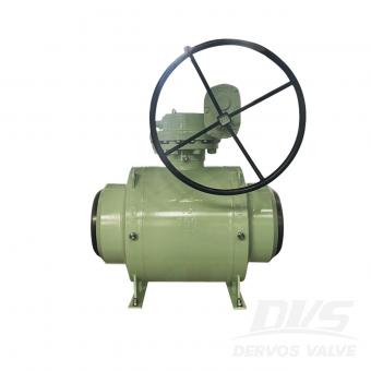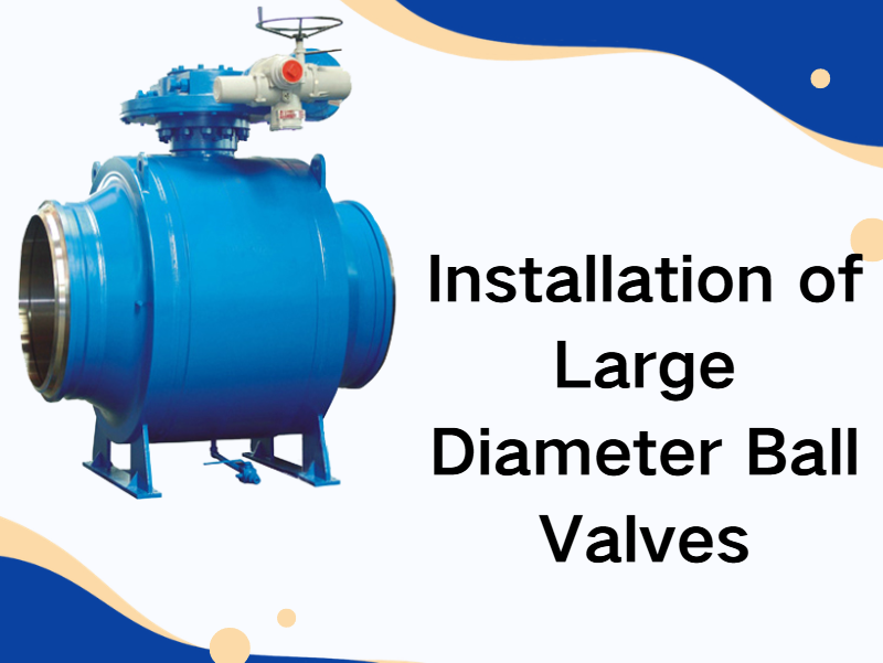
Large diameter ball valves are commonly used in industries such as petroleum and chemical processing, power generation, long-distance pipeline transportation, and large-scale water treatment systems. If installation is not performed correctly, it may lead to sealing leakage, valve jamming, or structural stress damage. Therefore, proper installation practices are essential to ensure long-term stable operation. 1. Pre-installation Inspection If pre-installation inspection is insufficient, operational failures are more likely to occur during service. First, inspect the valve body for transportation damage. If scratches, impact marks, or deformation are found on the valve body or sealing surfaces, installation should be stopped and the supplier should be contacted. Next, verify valve model, pressure rating, and connection standards. If the system design pressure does not match the valve pressure class, operational safety risks may occur. For example, if a low-pressure class valve is mistakenly used in a high-pressure pipeline system, the valve body may experience plastic deformation under water hammer impact. It is also necessary to check the condition of the ball surface and sealing rings. If there are scratches on the ball surface, sealing performance will be reduced. This is especially critical in gas transmission systems where micro-leakage is more likely. 2. Installation Direction Large diameter ball valves usually have a flow direction marking. If the installation direction is incorrect, the following problems may occur: If the fluid flow direction matches the design direction, the operating torque will remain more stable. If the valve is installed in reverse, the stem may experience increased mechanical load, which will accelerate stem wear during long-term operation. For double-seal bidirectional ball valves, although bidirectional flow is allowed, installation according to the marked flow direction is still recommended to ensure more uniform sealing stress distribution. In high-temperature or steam systems, if the installation direction is incorrect, thermal expansion may accelerate sealing ring aging. 3. Pipeline Stress Control Large diameter ball valves are heavy. If installed without proper support, additional bending moments may be transferred to flange connections. If pipeline systems experience axial displacement, pipeline supports should be installed for segmented fixation. If support structures are not provided, the valve body may bear long-term gravitational tensile load, eventually causing flange seal failure. It is generally recommended to install independent supports on both sides of large diameter ball valves. If the pipeline system is subject to thermal expansion and contraction, expansion compensation devices must be installed; otherwise, sealing surfaces may gradually fail. 4. Bolt Tightening Process Flange connections of large diameter ball valves usually ...

This year’s Dervos annual conference was noticeably more grand and well-organized than in previous years. In the morning session, each department delivered its annual work summary, reviewing key projects and achievements over the past year. Teams also openly shared the challenges encountered during implementation and the practical experience gained along the way. Through this cross-department exchange, everyone developed a clearer understanding of one another’s responsibilities and workflows, laying a stronger foundation for future collaboration and communication. In the afternoon session, the Outstanding Employee awards were presented. Each nominee shared their work achievements and practical experience, demonstrating a strong sense of responsibility and execution across different roles. It is precisely this proactive mindset, collaborative spirit, and down-to-earth working approach of Dervos employees that drives the team steadily toward its shared goals. Showing up on time every single day throughout the year — that’s quite an achievement. Ian has now received the Perfect Attendance Award for two consecutive years. During the annual conference, Dervos also presented medals and exclusive commemorative gifts to employees who have completed five years of service. Dervos values the long-term dedication and consistent commitment of its team members, and sincerely appreciates the trust and contributions they have made over the years. For many at Dervos, the company is not only a platform for professional growth, but also a stage where shared goals and collective efforts come to life. In the evening, the annual conference transitioned into the banquet segment. Performances and interactive games were seamlessly interspersed, creating a relaxed yet organized atmosphere. Laughter and cheers echoed throughout the venue, and in the moment the camera shutter clicked, the excitement and joy were captured in a single frame. Eric said: "Let’s dream together, DERVOS's dream. A dream where we all play a part, piece by piece, it becomes a reality." For Dervos, the annual meeting is not just about "summarizing the year," but about bringing our hearts together, strengthening our resolve in doing the same thing, and then continuing to move forward, step by step, with steady progress.
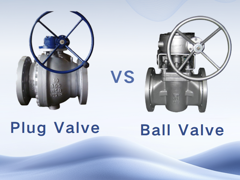
Ball valves and plug valves differ significantly in several aspects, including structure, operating principle, mode of operation, flow control capability, sealing performance, and application scenarios. These differences enable the two types of valves to perform distinct roles in their respective fields. Structural Differences The ball valve, a design evolved from the plug valve, utilizes a spherical element as its core component. By rotating the ball 90° around the stem axis, the valve can be opened or closed. Its structure is straightforward, consisting primarily of a spherical closure element with a through-bore housed within the valve body. In contrast, the structure of a plug valve is more complex. It comprises multiple components such as the valve body, bonnet, plug, seat, and stem. The closure element is a cylindrical or tapered plug that controls flow by rotating 90°, aligning or misaligning the port in the plug with the flow passage in the valve body to achieve opening or shutoff. Operating Principle The operating principle of a ball valve relies on the rotation of the ball to control the on-off flow of fluid. When the ball is in tight contact with the valve seat, the clearance between them is completely sealed, thereby preventing fluid leakage. When the ball rotates to a position disengaged from the seat, the fluid is allowed to flow freely through the passage inside the valve body. The operating principle of a plug valve differs in that it primarily controls the flow passage by rotating the plug element to open or close the valve. In a plug valve, the plug is connected to the stem and rotates together with it to achieve flow control. The closure element is a tapered plug with a port, and the flow passage is designed to be perpendicular to the axis of the plug. This configuration enables the plug valve to operate more efficiently and reliably during opening and closing. The operation of a ball valve is notably simple, requiring only a 90-degree rotation to achieve opening or closing. This design allows the flow passage to be opened or shut off quickly and smoothly when the ball is rotated by 90 degrees, providing both convenience and efficiency. In addition, ball valves offer relatively low flow resistance in the fully open or fully closed position, making them particularly suitable for applications that require rapid on-off operation. By contrast, the operation of a plug valve is comparatively more complex, as several turns are typically required to complete the opening or closing action. The valve plug is designed in a cylindrical or tapered form and regulates fluid flow through rotation. Nevertheless, plug valves demonstrate excellent performance in flow regulation, enabling precise adjustment of the flow passage diameter and accurate control of flow rate. However, due to the relatively complicated operating process, plug valves are not well suited for frequent operation...

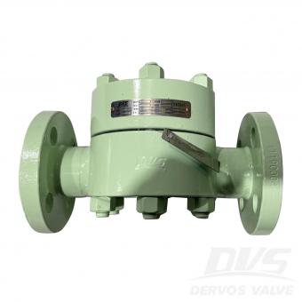
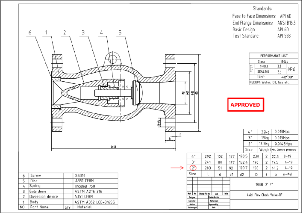
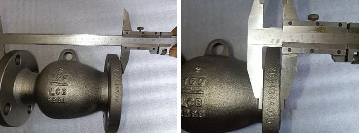
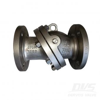
صمام فحص التدفق المحوري CL150 مقاس 2 بوصة مُصنَّع وفقًا لمعيار API 6D. جسم الصمام مصنوع من ASTM A352 LCB+316SS. يتميز بخصائص هيكلية للتدفق المحوري. طريقة توصيله هي التردد اللاسلكي (RF).
دفع:
30% when order confirmed, 70% before shipmentأصل المنتج:
chinaاللون:
Customizationميناء الشحن:
Shanghai, Chinaالمهلة:
30~60 days Ex Works after order confirmationMaterial:
ASTM A352 LCB+316SSMethod of Operation:
H.W.
|
يكتب |
صمام فحص التدفق المحوري |
|
مقاس |
2 بوصة |
|
ضغط |
CL150 |
|
اتصال |
ترددات الراديو |
|
مادة الجسم |
ASTM A352 LCB+316SS |
|
معيار التصميم |
API 6D |
|
وجها لوجه |
API 6D |
|
أبعاد الحافة النهائية |
ASME B16.5 |
|
رمز الاختبار والتفتيش |
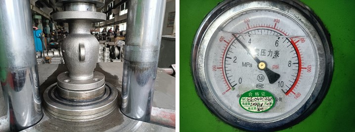
API 598 |
|
درجة حرارة |
-46 ~ 350 ° ج |
|
الوسيلة المناسبة |
المياه والنفط والغاز |
1. يقلل تصميم التدفق المحوري من انخفاض الضغط ويضمن تدفقًا سلسًا ومنخفض الاضطرابات.
2. تم تصنيعها وفقًا لمعيار API 6D مع أطراف RF، مما يوفر منعًا موثوقًا به للتدفق العكسي في أنظمة خطوط الأنابيب.
إذا كنت مهتما في منتجاتنا و تريد أن تعرف المزيد من التفاصيل,يرجى ترك رسالة هنا وسوف نقوم بالرد عليك بأسرع ما يمكن.
2inch صمام فحص فوهة محوري هو الحل المفضل لمنع تدفق العائد أو الصدمات في العملية الحرجة المعدات. شكرا على أنه LCB الجسم، والصمام قادر على درجة حرارة العمل وصولا إلى -46 درجة مئوية.
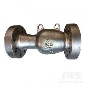
تم تصنيع صمام فحص التدفق المحوري 3 بوصة 1500LB وفقًا لمعيار API 6D. جسم الصمام مصنوع من A995 4A. إنه يتميز بالخصائص الهيكلية لنوع التدفق المحوري، والطول الهيكلي 473 مم. وضع الاتصال الخاص به هو RTJ.

صمام فحص التدفق المحوري مقاس 6 بوصات، سعة 300 رطل، مصنوع وفقًا لمعيار API594. جسم الصمام مصنوع من SS2205. يتميز بخصائص هيكلية من النوع الصامت، وطريقة توصيله هي نوع رقاقة.
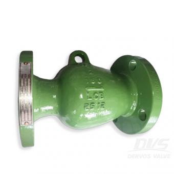
مصفاة السلة مقاس 6 بوصات سعة 150 رطل مصنوعة وفقًا لذلك لمعيار ASME B16.34. جسم الصمام مصنوع من ASTM A216 WCB. لديها الخصائص الهيكلية لنمط السلة، والغطاء المثبت بمسامير، مع العادم و سدادات التصريف. وضع الاتصال الخاص به هو RF.
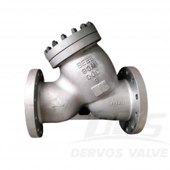
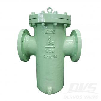
مصفاة من الفولاذ المصبوب على شكل حرف Y، مقاس 8 بوصات، 300 رطل، مصنوعة وفقًا لمعيار ASME B16.34. جسم الصمام مصنوع من مادة ASTM A216 WCB. يتميز بخصائص هيكلية مشابهة لنوع Y. طريقة توصيله هي التردد اللاسلكي (RF).
تم تصنيع الصمام الأعمى ذو الخط 10 بوصة 150LB وفقًا لمعيار ASME B16.34. جسم الصمام مصنوع من A105. له الخصائص الهيكلية المضادة للتنقيط. وضع الاتصال الخاص به هو RF. وله وضع تشغيل التوربين.
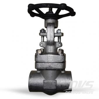
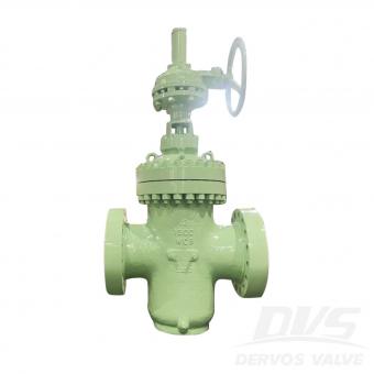
تم تصميم صمام البوابة مقاس 1 بوصة 800 رطل وفقًا لواجهة برمجة التطبيقات 602 مع تشغيل sw و handwheel. يحتوي صمام البوابة f316 من الفولاذ المقاوم للصدأ على غطاء محرك مثبت بمسامير ومسمار خارجي ونير.
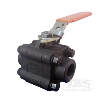
الصين كربون الصلب الكرة صمام مزود عروض 3 قطعة صمام الكرة نوع موقف، ASTM A105N، فئة 800، 1 بوصة، كرة عائمة مجانية، API 608، بكالوريوس 5351.
تم تصنيع صمام فحص القرص المائل 3 بوصة 150LB وفقًا لمعايير API 6D وBS1868. جسم الصمام مصنوع من ASTM A351 CF8M. إنه يتميز بالخصائص الهيكلية لنوع القرص المائل وغطاء الترباس. وضع الاتصال الخاص به هو RF.
يتميز صمام السدادة المشحم مقاس 8 بوصات بهيكل نوع مقلوب ومتوازن الضغط. إن صمام القابس المعدني ذو الحواف مناسب لتطبيق الغاز الطبيعي. تفاصيل سريعة نوع قابس كهرباء صمام بحجم 8 " ضغط التصميم 300 رطل اعمال بناء مشحم نوع ، نوع مقلوب ، نوع متوازن الضغط ، جالس معدني نوع الاتصال ذات حواف الإتصال عملية هيأ تعمل كود التصميم api 599 وجها لوجه اسمى ب 16.10 نهاية الاتصال اسمى ب 16.5 الضغط & أمبير ؛ مؤقت اسمى ب 16.34 اختبار & أمبير ؛ تفتيش واجهة برمجة تطبيقات 598 مواد الجسم WCC نطاق درجة حرارة -29 ℃ ~ + 425 ℃ تطبيق ماء، النفط والغاز البعد صف دراسي بحجم 1 1/2 2 2 1/2 3 4 6 8 10 12 300 ب 191 216 241 283 305 403 419 457 502 ج 156 165 191 210 254 318 381 445 521 د 20.6 22.2 25.4 28.3 31.8 36.5 41.3 47.6 50.8 ه 169 178 & emsp؛ 219 235 362 & emsp؛ & emsp؛ & emsp؛ F 106 118 & emsp؛ 143 165 187 248 300 392 س 73 92.1 105 127 157 216 270 324 381 الوزن (rf) 16 21 & emsp؛ 38 60 101 192 281 508 المعرفة ذات الصلة ما هو صمام التوصيل؟ صمام القابس هو صمام رباعي الدوران الذي يدور قابسه حول الخط المركزي لجسم الصمام لتحقيق وظيفة التشغيل. يتم استخدام صمام القابس لقطع وتوزيع وتغيير تدفق التدفق. حاليًا ، تُطبق صمامات السدادة بشكل أساسي على الحجم الصغير ودرجة الحرارة العادية وظروف الضغط المنخفض. مزايا صمام القابس موضحة أدناه:-فتح سريع وإغلاق الصمام- مقاومة السوائل الصغيرةخدمة موثوقة ضد التسرب-تتوفر صيانة مضمنة
يتم إجراء تغيير على صمام 2 "300LB وفقًا لمعيار ASME B16.34. جسم الصمام مصنوع من ASTM A216 WCB. هو - هي لديه الخصائص الهيكلية لغطاء المكونات، والمواد الداخلية الشاملة هو F316L. وضع الاتصال الخاص به هو RF. ولها وضع تشغيل عقارب.
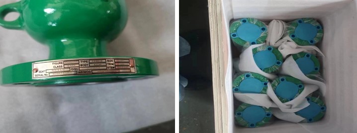
معايير المنتج يكتب صمام كروي محوري مقاس 2 بوصة × 1-1/2 بوصة ضغط 600 رطل اتصال الترددات اللاسلكية عملية مقبض مزود بقفل مادة الجسم ASTM-A105 معيار التصميم API 6D وجهاً لوجه ASME B16. 10 نهايات الفلنجة معيار ASME B16.5 الاختبار والفحص شفرة API 6D درجة حرارة - 2 0 ~ 80 درجة مئوية الوسيلة المناسبة الماء والنفط والغاز سمات 1. يضمن التصميم المثبت على محور الدوران التشغيل المستقر والحد الأدنى من عزم الدوران لتشغيل الصمام بسلاسة. 2. مصنف لتحمل 600 رطل ومبني وفقًا لمعايير API 6D باستخدام فولاذ الكربون A105F، مما يوفر احتواءً موثوقًا للضغط. الرسم الفني فحص الأبعاد اختبار الضغط تقرير التفتيش


حقوق النشر © 2015-2026 DERVOS VALVE CO.,LTD.كل الحقوق محفوظة مدونة / خريطة الموقع / XML / سياسة الخصوصية