تُستخدم صمامات البوابة والصمامات العمياء لعزل خطوط الأنابيب، لكنها تعمل وفق مبادئ مختلفة بشكل أساسي. في أنظمة الأنابيب الصناعية، إذا كان الهدف هو عزلة جسدية حقيقية (في حالة العزل الإيجابي)، فإن الصمام الأعمى (صمام أعمى / صمام خط أعمى) يكون عمومًا أكثر موثوقية من الصمامات التقليدية. فبدلاً من الاعتماد على إحكام إغلاق المقعد، فإنه يعزل الوسط من خلال لوحة عمياء صلبة وهذا ما يحدد نطاق تطبيقه وقيمته الهندسية. يمكن فهم الخصائص الرئيسية للصمام الأعمى من منظور هندسي على النحو التالي: 1. العزلة الجسدية المطلقة لو انعدام التسرب إذا كان ذلك مطلوبًا، فإن الصمامات التقليدية (مثل صمامات البوابة أو صمامات الكرة) تشكل خطرًا، لأن أدائها يعتمد على سلامة الختم. تتبع الصمامات العمياء منطقًا مختلفًا: ▶ إذا تم إدخال صفيحة صلبة، فسيتم حجب التدفق تمامًا ▶ إذا تم وضع اللوحة العمياء بشكل صحيح، فلن يكون فشل الإحكام مصدر قلق بعد الآن وهذا يجعل الصمامات العمياء أكثر ملاءمة لـ: ● عزل خطوط أنابيب النفط والغاز ● مواد قابلة للاشتعال (البترول، الغاز الطبيعي المسال، المواد الكيميائية) ● نظام بخار عالي الحرارة s الخلاصة الهندسية: إذا كان المشروع يتطلب عزلاً يمكن التحقق منه، فيجب إعطاء الأولوية للصمام الأعمى على الصمامات الصناعية التي تعتمد على منع التسرب. 2. إمكانية التشغيل المباشر تتطلب الستائر التقليدية ذات المجرفات والفواصل عادةً تفكيك الحافة، مما يزيد من تعقيد التشغيل ويؤدي إلى مخاطر تتعلق بالسلامة. الصمامات العمياء (مثل صمام ستائري منزلق تم تصميم صمامات التأرجح والستائر ذات الأغطية المتحركة بنهج مختلف: ▶ إذا تطلب الأمر التبديل المتكرر بين التشغيل والصيانة، فيجب تقليل التدخل اليدوي إلى الحد الأدنى. ▶ إذا لم يُسمح بالإغلاق، فيجب إجراء عملية التحويل في ظل ظروف خط الأنابيب المضغوط (رهناً بالتصميم المحدد). لذلك: ● صمام انزلاقي مغلق: مناسب للمساحات المحدودة ومتطلبات التشغيل الآلي العالية ● صمام الستارة المتأرجح: بنية بسيطة، مناسبة لتردد التبديل المتوسط إلى المنخفض ● صمام حجب الرؤية على شكل نظارة : مناسب للتشغيل بتردد منخفض والمشاريع الحساسة للتكلفة الخلاصة الهندسية: إذا كانت الصيانة متكررة أو كان الإيقاف غير ممكن، فيجب إعطاء الأولوية لصمام مغلق مزود بإمكانية التشغيل المباشر. 3. الموثوقية الميكانيكية لا تعتمد موثوقية الصمام الأعمى على أنظمة منع التسرب المعقدة، بل على: ● الاستقرار الهيكلي الميكانيكي ● قوة المادة (مثل A105، WCB، F22، LF2) ● طريقة التشغيل (يدوي، أو يعمل بالتروس، أو هيدروليكي) ▶ إذا كانت ظروف التشغيل تتضمن درجة حرارة عالية أو ضغطًا عاليًا أو مواد أكالة، فإن الصمامات التي تعتمد على منع التسرب تكون أكثر عرضة للفشل ▶ في حال استخدام صمام مغلق، فإن الخطر الأساسي يتحول إلى التصميم الهيكلي وآليات التشغيل تشمل التطبيقات النموذجية ما يلي: ● أنظمة عزل المصافي ● مصانع البتروكيماويات ● خطوط البخار في محطة توليد الطاقة الخلاصة الهندسية: إذا كانت عواقب فشل النظام بالغة الأهمية، فيجب إعطاء الأولوية للحلول الموثوقة هيكليًا على تصميمات الصمامات التي تعتمد على منع التسرب. 4. تصميم نظام التعشيق الآمن في المشاريع العملية، يُعد الخطأ التشغيلي أحد المخاطر الرئيسية. تُجهز الصمامات العمياء عادةً بما يلي: ● قفل الوضع الميكانيكي ● أجهزة التعشيق لمنع التشغيل الخاطئ ● مؤشر واضح لوضع الفتح/الإغلاق ▶ إذا كانت مادة العملية قابلة للاشتعال أو سامة، فيجب تقليل خطر سوء التشغيل إلى أدنى حد. ▶ في حال استخدا...
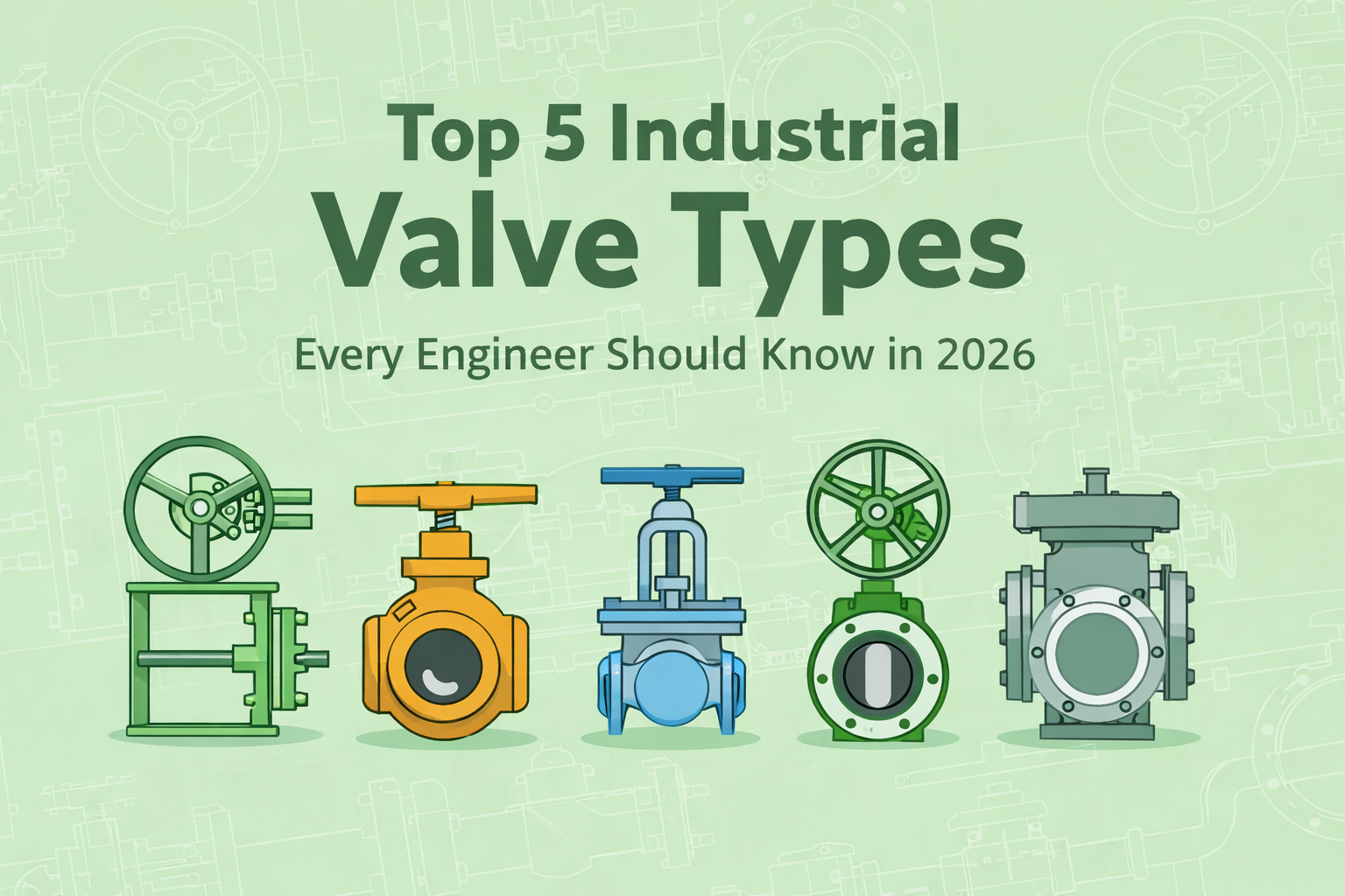
يُعد اختيار نوع الصمام الصناعي المناسب أحد أهم القرارات في تصميم النظام. فالاختيار غير المناسب، حتى مع استخدام صمامات عالية الجودة، قد يؤدي إلى التسرب، وفقدان الضغط، والاهتزاز، والحاجة إلى صيانة متكررة، وانخفاض كفاءة التشغيل على المدى الطويل. يغطي هذا الدليل أنواع الصمامات الصناعية الرئيسية ، وتطبيقاتها ومزاياها وقيودها، إلى جانب رؤى عملية لمساعدتك في اختيار الصمام المناسب لمشروعك في عام 2026. ما هي أنواع الصمامات الصناعية؟ تشير أنواع الصمامات الصناعية إلى تصاميم الصمامات المختلفة المستخدمة للتحكم في تدفق السوائل في أنظمة الأنابيب أو تنظيمه أو عزله. كل نوع مصمم لوظيفة محددة، مثل الإغلاق أو الخنق أو منع التدفق العكسي، ويُعد اختيار النوع الصحيح أمرًا بالغ الأهمية لسلامة النظام وكفاءته. خمسة أنواع رئيسية من الصمامات الصناعية وتطبيقاتها 1. صمام كروي الأفضل لـ: الإغلاق السريع وانخفاض الضغط تستخدم صمامات الكرة كرة دوارة ذات تجويف مستقيم. وعند فتحها بالكامل، فإنها توفر مقاومة ضئيلة، مما يجعلها واحدة من أكثر الخيارات كفاءة لنقل السوائل. التطبيقات الشائعة: ● خطوط أنابيب النفط والغاز ● أنظمة الضغط العالي ● عمليات تشغيل/إيقاف متكررة ملاحظات الاختيار: ● تصميمات الفتحة الكاملة تقلل من فقد الطاقة ● تتميز صمامات الكرة ذات المقعد المعدني بأداء أفضل في الظروف الكاشطة أو ذات دورات التشغيل العالية تجنبه في الحالات التالية: يلزم التحكم الدقيق في التدفق. قد يؤدي الخنق باستخدام صمام كروي إلى تلف أسطح منع التسرب بمرور الوقت. 2. صمام البوابة الأفضل لـ: خدمة العزل ذات مقاومة التدفق المنخفضة تعمل صمامات البوابة عن طريق رفع البوابة من مسار التدفق. وهي تُستخدم على نطاق واسع في خطوط الأنابيب ذات الأقطار الكبيرة حيث يكون التشغيل الكامل أو الإغلاق الكامل مطلوبًا. التطبيقات الشائعة: ● خطوط أنابيب نقل الطاقة لمسافات طويلة ● أنظمة معالجة المياه ● خطوط البخار ذات درجة الحرارة العالية ملاحظات الاختيار: ● انخفاض الضغط شبه معدوم عند الفتح الكامل ● توفر صمامات البوابة الإسفينية إحكامًا أفضل في ظروف درجات الحرارة العالية تجنبه في الحالات التالية: يتطلب الأمر تشغيلًا أو تحكمًا متكررًا. صمامات البوابة غير مصممة للتشغيل المتكرر. 3. صمام كروي الأفضل لـ: تنظيم التدفق بدقة تقوم صمامات الكرة الأرضية بدفع السائل عبر مسار تدفق متحكم فيه، مما يسمح بالتحكم الدقيق في التدفق وثباته. التطبيقات الشائعة: ● أنظمة البخار ● العمليات ذات درجات الحرارة العالية ● تطبيقات تنظيم التدفق ملاحظات الاختيار: ● أداء ممتاز في التحكم في السرعة ● تشغيل مستقر في ظل ظروف تدفق متقلبة تجنبه في الحالات التالية: يجب تقليل انخفاض الضغط إلى أدنى حد. صمامات الكرة الأرضية بطبيعتها تخلق مقاومة تدفق أعلى. 4. صمام عدم الرجوع الأفضل لـ: منع التدفق العكسي التلقائي تعمل صمامات الفحص تلقائيًا بناءً على اتجاه التدفق، مما يمنع التدفق العكسي الذي قد يتسبب في تلف المعدات. التطبيقات الشائعة: ● خطوط تصريف المضخة ● أنظمة الضواغط ● شبكات أنابيب العمليات ملاحظات الاختيار: ● تعمل صمامات الفحص المزدوجة والصامتة على تقليل ظاهرة الطرق المائي. ● يُعدّ اختيار المقاس المناسب والتركيب الصحيح أمراً بالغ الأهمية لتجنب اهتزاز القرص. تجنبه في الحالات التالية: يلزم إيقاف التشغيل أو العزل اليدوي. 5. صمام مغلق (صمام مغلق للخط) الأفضل لـ: العزل الإيجابي وأقصى درجات الأمان توفر الصمامات العمياء عزلاً مادياً عن طريق إدخال صفيحة صلبة في خط الأنابيب. وعلى عكس الص...
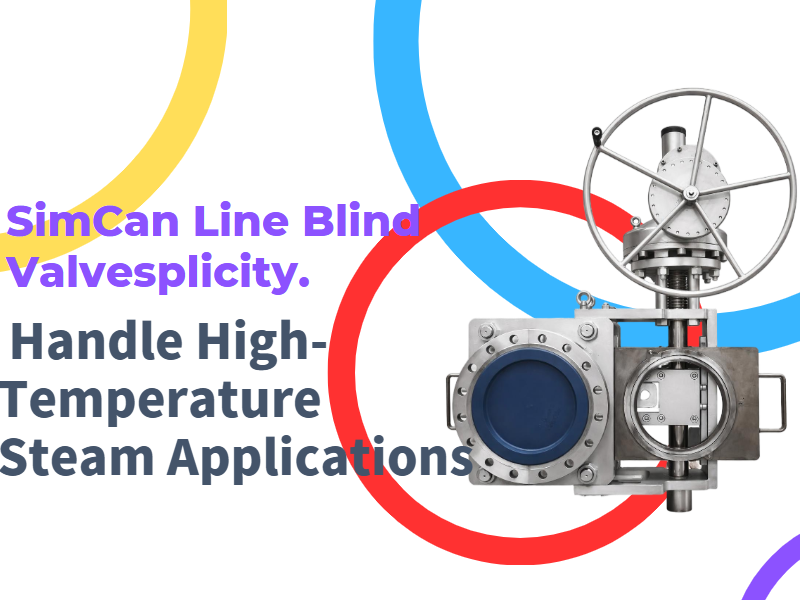
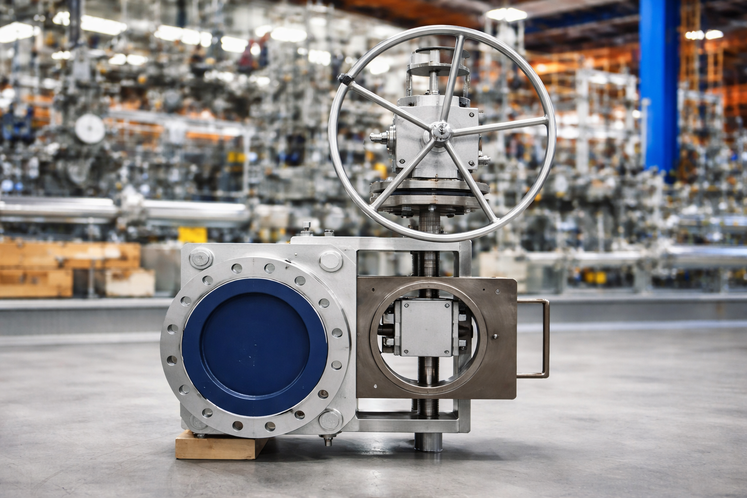
حديثاً، صمام ديرفوس ساعدت عميلاً في المجر على التغلب على تحدٍ شائع في أنظمة البخار الصناعية: كيفية عزل خطوط الأنابيب ذات درجات الحرارة العالية بأمان دون حدوث تسرب أو توقف. نظراً لتشغيل النظام ببخار مشبع عند درجة حرارة تقارب 250 درجة مئوية، وتعرضه لدرجات حرارة منخفضة تصل إلى -39 درجة مئوية، فقد تطلب نظام العميل حلاً متيناً وموثوقاً. غالباً ما تفشل الصمامات التقليدية في الحفاظ على إحكام الإغلاق في مثل هذه الظروف، كما تتطلب طرق العزل التقليدية تخفيض ضغط الخط، مما يزيد من وقت التوقف ومخاطر التشغيل. ولمعالجة هذه التحديات، قامت شركة ديرفوس بتوريد DN400 PN40 صمام خطي منزلق مغلق صُممت هذه الصمامات خصيصاً لتناسب الظروف القاسية للمشروع. وتتيح آلية الإغلاق المنزلقة للمشغلين التبديل بين وضعيتي التدفق والعزل دون الحاجة إلى تفريغ ضغط النظام، مما يعزز السلامة والكفاءة أثناء الصيانة. مصنوع من فولاذ 20GML المطروق وهيكل مانع للتسرب من الفولاذ المقاوم للصدأ المعدني، صمام يُقدّم أداءً موثوقًا به في كلٍّ من البخار ذي درجات الحرارة العالية والظروف المناخية الخارجية القاسية. يُقلّل تصميمه ذو الفتحة الكاملة من مقاومة التدفق، بينما يضمن المُشغّل اليدوي ذو التروس الدودية تشغيلًا سلسًا ومُتحكّمًا به حتى في الأحجام الكبيرة ومعدلات الضغط العالية. كما تُقلّل ميزات السلامة، مثل أجهزة منع التشغيل الخاطئ وهياكل الألواح الواقية، من مخاطر الأخطاء أثناء المناولة. منذ تركيبه، مكّن الصمام من التشغيل الخالي من التسريبات، وإجراءات الصيانة الأكثر أمانًا، والأداء المستقر في درجات الحرارة القصوى. صُمم الصمام ليدوم لأكثر من 30 عامًا، مما يوفر حلاً طويل الأمد قليل الصيانة، ويمنح العميل الثقة في موثوقية نظام البخار وسلامته. يسلط هذا المشروع الضوء على كيفية تمكن صمام الخط المنزلق المصمم بعناية من حل تحديات العزل الحرجة في تطبيقات البخار ذات درجات الحرارة العالية، حيث يج

الصمام الأعمى الخطي (صمام النظارات) هو نوع من صمام البوابة الذي يقطع وسيط الغاز يدويًا أو كهربائيًا أو هوائيًا أو هيدروليكيًا. وهي مقسمة عمومًا إلى صمام كهربائي أعمى ، وصمام أعمى هيدروليكي ، وصمام مغلق بسدادة ، وصمام أعمى كهربائي مفتوح.
دفع:
30% when order confirmed, 70% before shipmentأصل المنتج:
Chinaاللون:
Customizationميناء الشحن:
Shanghai, Chinaالمهلة:
30~60 days Ex Works after order confirmationوصف المنتج
يستخدم الصمام الأعمى الخطي على نطاق واسع في نظام إدارة الغاز المتوسط للمؤسسات الصناعية والتعدين والبلديات وحماية البيئة وغيرها من الصناعات ، خاصة لقطع الغازات الضارة والسامة والقابلة للاشتعال. يعتبر الصمام الأعمى الخطي مناسبًا أيضًا لاستخدامه كلوحة عمياء لمحطة الأنبوب لتقصير وقت الصيانة أو تسهيل توصيل نظام خط الأنابيب الجديد.
سمات
1. هيكل جديد وخفيف الوزن وصغر الحجم وعملية مريحة وعمل سريع وأداء موثوق به ؛
2. الإغلاق الإيجابي المطلق ، عدم الحاجة إلى انتشار الأنابيب ، الختم غير متأثر بعدم محاذاة الأنابيب.
رسم تقنى _ رسم عن طريق الكمبيوتر

مواصفات الصمامات الخطية العمياء
| وصف |
معيار |
| مقاس |
DN 15 (1/2 بوصة) إلى DN 1200 (48 بوصة) |
| فئة الضغط |
ASME 150 # ، 300 # ، 600 # |
| مادة الجسم |
|
| لوحة النظارات |
ستانلس ستيل |
| ينبع |
ستانلس ستيل |
| البراغي |
خليط معدني |
| يا الخواتم |
فيتون ، بونا إن |
| درجة حرارة |
232 درجة مئوية / 450 درجة فهرنهايت |
| اتصال الأنابيب |
أبيض وأسود / RF |
| شهادة |
ASME ، DIN ، ISO ، PED |
المعايير الهندسية للخطوط العمياء للصمامات
| معيار ASME |
وصف |
| ب 16.5 |
شفة الأنابيب والتجهيزات ذات الحواف |
| ب 16.34 |
الصمامات - ذات حواف وملولبة ونهايات لحام |
| B31.1 |
أنابيب الطاقة |
| ASTM F1020 |
خط الصمامات العمياء للتطبيقات البحرية |
| كود ASME B&PV |
الوصف (رمز وعاء الغلاية والضغط) |
| القسم الثاني |
مادة |
| القسم الثامن |
قواعد بناء أوعية الضغط |
| القسم التاسع |
مؤهلات اللحام والنحاس |
| معيار API |
وصف |
| ASME 16.48.001 |
الفراغات الخط الصلب للتكرير |
| API 598 |
فحص الصمام واختباره |
| API 2217 |
مبادئ توجيهية للعمل في الأماكن المحصورة في صناعة البترول |
| آحرون |
وصف |
| ISO 9001 |
نظام ادارة الجودة |
| NACE MR0175 |
تكسير إجهاد الكبريتيد والتآكل الإجهادي |
إذا كنت مهتما في منتجاتنا و تريد أن تعرف المزيد من التفاصيل,يرجى ترك رسالة هنا وسوف نقوم بالرد عليك بأسرع ما يمكن.
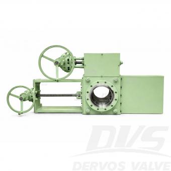
يتم استخدام الستائر الخطية في أنظمة خطوط الأنابيب عندما تكون هناك حاجة إما للإغلاق الكامل أو انتقال التدفق دون عوائق دون انخفاض كبير في الضغط. يتيح تصميم THD (التصميم من خلال الفتحة) إجراء تعديلات سريعة وسلسة في الموضع. يتميز متغير شريحة THD بتكوين متعدد البراغي، مما يجعل من السهل التشغيل بأبعاد منخفضة وجهاً لوجه. إن تضمين مسامير الجسم الإضافية يجعل هذا النمط مناسبًا بشكل خاص لتطبيقات الضغط العالي.
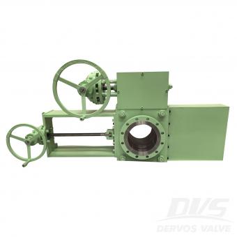
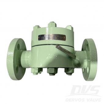
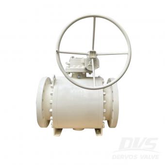
تم تصنيع الصمام الأعمى ذو الخط 10 بوصة 150LB وفقًا لمعيار ASME B16.34. جسم الصمام مصنوع من A105. له الخصائص الهيكلية المضادة للتنقيط. وضع الاتصال الخاص به هو RF. وله وضع تشغيل التوربين.
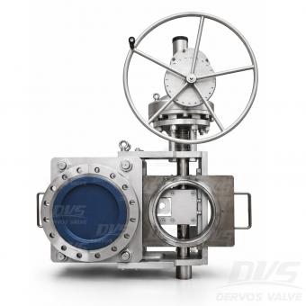
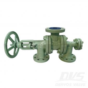
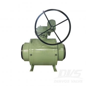
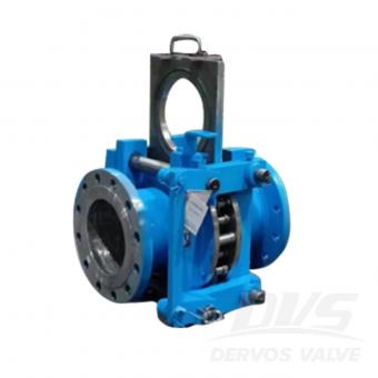
صمام DN400 PN40 المنزلق ذو الغطاء المغلق مصنوع وفقًا لمعيار EN12516-1/2. جسم الصمام مصنوع من الفولاذ LF2. صُمم الصمام للعمل مع البخار بدرجة حرارة تشغيل 250 درجة مئوية، وضغط تشغيل 1.3 ميجا باسكال، وضغط تصميم 2 ميجا باسكال، ونطاق درجة حرارة تصميم من -39 درجة مئوية إلى +350 درجة مئوية، ونطاق درجة حرارة محيطة من -39 درجة مئوية إلى +34.7 درجة مئوية. طريقة توصيله هي التردد اللاسلكي (RF). وهو مزود بتروس. وضع التشغيل. معايير المنتج يكتب صمام انزلاقي مغلق مقاس DN400 ضغط PN40 اتصال الترددات اللاسلكية عملية معدات مادة الجسم A182 LF2 معيار التصميم EN12516-1/2 وجهاً لوجه معايير الموردين أبعاد الشفة GOST 33259-النوع ب قانون الاختبار والتفتيش EN12266-1/2 درجة حرارة -29 ~ 120 درجة مئوية الوسيلة المناسبة الماء والنفط والغاز سمات 1. يوفر التصميم المصنوع من قطعة واحدة والمطروقة سلامة هيكلية عالية وأداءً مانعًا للتسرب تحت ضغط PN40. 2. آلية الانزلاق العمياء المزودة بشفة ترددات الراديو تسمح بعزل أجزاء خط الأنابيب بشكل آمن وفعال. الرسم الفني فحص الأبعاد اختبار الضغط تلوين لوحة الاسم والتغليف تقرير التفتيش
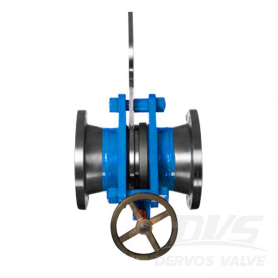
صمام انزلاقي مغلق بقطر 10 بوصات ووزن 150 رطلًا مصنوع وفقًا لمعيار ASME B16.34. جسم الصمام مصنوع من الألومنيوم A105. يتميز بتصميم مقاوم للتقطير. يعمل بنظام الترددات اللاسلكية (RF). مزود بتوربين. وضع التشغيل. معايير المنتج يكتب صمام انزلاقي مغلق مقاس 10 بوصات ضغط 150 رطل اتصال الترددات اللاسلكية عملية توربين مادة الجسم A105 معيار التصميم ASME B16.34 وجهاً لوجه معيار الشركة المصنعة أبعاد الشفة معيار ASME B16.5 قانون الاختبار والتفتيش API 598 درجة حرارة -29 ~ 150 درجة مئوية الوسيلة المناسبة الماء والنفط والغاز سمات 1. آلية الانزلاق التي تعمل بالتوربينات تتيح التشغيل السلس والفعال لعزل خطوط الأنابيب ذات الأقطار الكبيرة. 2. يضمن الهيكل المصنوع من الفولاذ الكربوني A105 المطروق مع شفة RF القوة والمتانة وأداء منع التسرب الموثوق به. الرسم الفني فحص الأبعاد اختبار الضغط تلوين لوحة الاسم والتغليف تقرير التفتيش
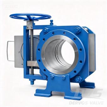
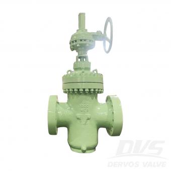
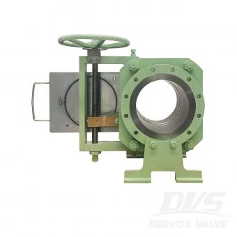
مقدمة يوفر صمام الخط المنزلق ذو الفئة 300 مقاس 10 بوصات عزلًا إيجابيًا مطلقًا لخطوط الأنابيب ذات الضغط المتوسط إلى العالي، حيث يجمع بين موثوقية الحاجز المادي الصلب وبساطة التشغيل اليدوي بواسطة البرغي. بخلاف الصمامات التقليدية التي تعتمد على مقاعد معرضة للتآكل، تُنشئ آلية الإغلاق المنزلقة حاجزًا ماديًا حقيقيًا، مما يضمن عدم حدوث أي تسريب أثناء الصيانة دون الحاجة إلى تخفيض ضغط النظام. وهذا يقلل بشكل كبير من وقت التوقف ويعزز سلامة العاملين. يوفر التصميم اليدوي الذي يعمل بالبرغي حركة دقيقة ومتحكم بها للوحة العمياء، مع قدرة القفل الذاتي المتأصلة للحفاظ على الوضع تحت الضغط - وهو مثالي للتطبيقات التي قد لا تتوفر فيها الطاقة الكهربائية أو الهوائية أو قد لا تكون مفضلة. صُمم هذا الصمام وفقًا لمعيار ASME B16.34 مع حواف RF وفقًا لمعيار ASME B16.5، وهو متوفر من الفولاذ الكربوني المطروق (A105) أو الفولاذ المقاوم للصدأ أو سبائك معدنية لتناسب ظروف التشغيل. تخضع كل وحدة لاختبار ضغط بنسبة 100% وفقًا لمعيار API 598. يُعد هذا التكوين ذو العشر بوصات من الفئة 300 خيارًا شائعًا لخطوط أنابيب البخار والنفط والغاز والمواد الكيميائية. تتوفر أحجام أخرى من بوصة واحدة إلى 60 بوصة وفئات ضغط تصل إلى الفئة 2500 ضمن سلسلة صماماتنا العمياء الكاملة. فتحة شريحة THD سمات 1. برغي يدوي التشغيل مع قفل ذاتي تتيح آلية التثبيت اللولبية الدقيقة وضع اللوحة العمياء بسلاسة وتحكم. وتحافظ آلية القفل الذاتي على الوضع تحت الضغط دون الحاجة إلى أجهزة كبح إضافية. 2. العزلة الجسدية المطلقة تُشكل الصفيحة العمياء الصلبة حاجزًا حقيقيًا، مما يضمن عدم حدوث أي تسرب أثناء الصيانة - على عكس الصمامات التي تعتمد على المقعد والتي يمكن أن تتآكل أو تتدهور بمرور الوقت. 3. التشغيل المباشر بدون تخفيف الضغط تتيح آلية الانزلاق التبديل بين وضعيات التدفق والوضعيات المغلقة دون الحاجة إلى تفريغ النظام، مما يقلل من وقت التوقف وفقدان المنتج. 4.10 بوصة الفئة 300 - التوازن الأمثل يوفر قدرة ضغط أعلى من الفئة 150 مع كونه أكثر اقتصادية من الفئة 600، مما يجعله خيارًا متعدد الاستخدامات لمجموعة واسعة من التطبيقات الصناعية. 5. هيكل من الفولاذ الكربوني المطروق يوفر الهيكل المصنوع من سبيكة A105 قوة عالية ومقاومة للصدمات وأداءً موثوقًا به في ظل دورات التغير الحراري. 6. تم اختباره وفقًا لمعيار API 598 يضمن الاختبار الهيدروستاتيكي والهوائي بنسبة 100% أداءً محكمًا ضد التسرب قبل الشحن. المواصفات القياسية المعلمة مواصفة يكتب صمام خطي منزلق مقاس 10 بوصة (DN250) تصنيف الضغط الفئة 300 (PN50) اتصال شفة الترددات الراديوية، ASME B16.5 عملية يدوي التشغيل بالبرغي (قفل ذاتي) مادة الجسم فولاذ كربوني مطروق A105 (تتوفر سبائك أخرى) مادة الختم / المقعد معدن إلى معدن (الفولاذ المقاوم للصدأ + الجرافيت) معيار التصميم ASME B16.34 البعد وجهاً لوجه وفقًا لمعيار ASME B16.10 أو معيار الشركة المصنعة الاختبار والفحص API 598 (هيدروستاتيكي وهوائي بنسبة 100%) نطاق درجة الحرارة من -29 درجة مئوية إلى +425 درجة مئوية (حسب نوع الختم) الوسائط المطبقة البخار، النفط، الغاز، الماء، الهيدروكربونات طلب عزل خطوط الأنابيب، مصافي النفط، مصانع البتروكيماويات، توليد الطاقة الرسم الفني خيارات تصميم مرنة تكوينات مصممة �


حقوق النشر © 2015-2026 DERVOS VALVE CO.,LTD.كل الحقوق محفوظة مدونة / خريطة الموقع / XML / سياسة الخصوصية