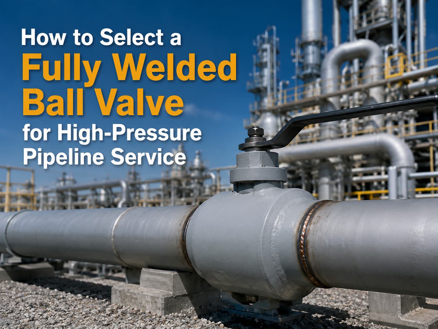
An API 602 forged gate valve is used for compact, small-bore gate valve service in petroleum, natural gas, chemical, power, and industrial piping. To specify the right design, confirm size, pressure class, material, bonnet type, end connection, port type, trim, seat, testing standard, and service conditions. What Is an API 602 Forged Gate Valve? An API 602 forged gate valve is a compact steel gate valve manufactured to API 602 requirements. API 602 covers gate, globe, and check valves for sizes DN 100 / NPS 4 and smaller in petroleum and natural gas industry applications. Unlike large cast steel gate valves, forged gate valves are usually selected for smaller piping systems where pressure, temperature, vibration, or compact installation matters. Forged construction provides a dense material structure, which is useful for high-pressure and critical service. In simple terms, API 602 is often the better fit when the line is small but the service is demanding. When Should You Use an API 602 Forged Gate Valve? Use an API 602 forged gate valve when the application requires reliable isolation in a compact piping system. It is commonly used in refineries, chemical plants, power plants, oil and gas facilities, steam lines, vents, drains, and utility systems. Typical use cases include: ● Small-bore high-pressure lines ● Steam and condensate service ● Process isolation ● Skid-mounted systems ● Drain and vent connections ● Instrument and auxiliary piping ● Oil, gas, and petrochemical service For larger line sizes or heavy-duty cast steel applications, API 600 may be more appropriate. API 602 and API 600 should not be treated as interchangeable standards. Key Design Choices to Specify Do not specify an API 602 forged gate valve only by size and pressure class. The purchase requirement should define the full valve design. Important items include: Item What to Confirm Size DN / NPS size and bore requirement Pressure class Class 800, 1500, 2500, or project requirement Material A105, F304, F316, F11, F22, LF2, or other grade Bonnet type Bolted bonnet, welded bonnet, or pressure seal End connection Socket weld, threaded, butt weld, or flanged Port Full port or regular port Trim Stem, wedge, seat, and hardfacing material Operation Handwheel, gearbox, or actuator if required Testing API 598 or project-specified testing These details affect sealing, pressure capability, maintainability, and installation. Bonnet and End Connection Selection Bonnet type should match pressure, temperature, and maintenance needs. Bolted bonnet designs are common and easier to service. Welded bonnet designs reduce potential leakage paths but are less convenient to disassemble. Pressure seal bonnets may be considered for higher-pressure service, depending on the design and project requirement. End connection is equally important. Socket weld ends are common for small-bore forged valves. Threaded ends may be...
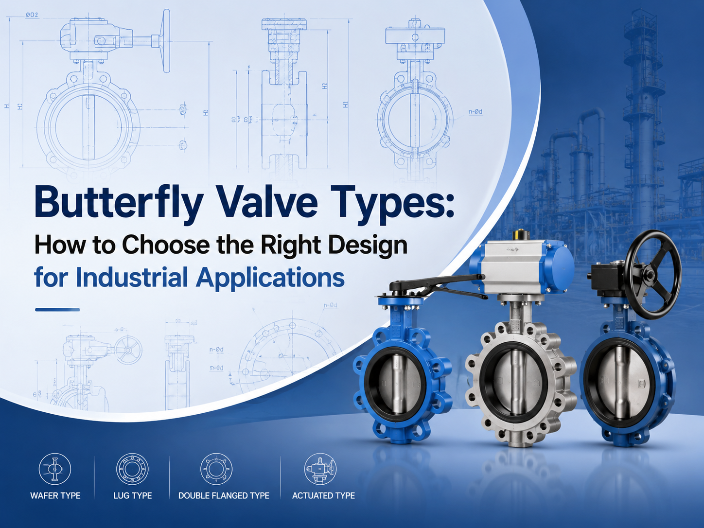
تشمل الأنواع الرئيسية لصمامات الفراشة الصمام متحدة المركز، والصمام مزدوج الإزاحة، والصمام ثلاثي الإزاحة، والصمام الرقائقي، والصمام ذو العروات، والصمام ذو الحواف، والصمام ذو المقعد المرن، والصمام ذو المقعد المعدني، والصمام اليدوي، والصمام الهوائي، وصمام الفراشة الكهربائي. يعتمد الاختيار الصحيح على الضغط ودرجة الحرارة والوسيط ومتطلبات التسرب ومساحة التركيب وتكرار التشغيل. ما هي الأنواع الرئيسية لصمامات الفراشة؟ تُصنَّف صمامات الفراشة عادةً حسب تصميم القرص، وطريقة توصيل الجسم، ومادة المقعد، وطريقة التشغيل. هذا التصنيف مهم لأن صمامين قد يُسمَّيان كلاهما صمامات فراشة، لكن حدود الخدمة الخاصة بهما قد تكون مختلفة جدًا. يستخدم صمام الفراشة قرصًا دوارًا لعزل التدفق أو تنظيمه. وبفضل هيكله المدمج ووزنه الخفيف وتشغيله بربع دورة، يُستخدم على نطاق واسع في معالجة المياه ومحطات الطاقة والمعالجة الكيميائية وأنظمة التدفئة والتهوية وتكييف الهواء والأنظمة البحرية وخطوط الأنابيب الصناعية العامة. بالنسبة للمشترين، لا يتمثل السؤال الرئيسي ببساطة في «أي نوع أرخص؟» بل في «أي نوع يمكنه تحمل الضغط ودرجة الحرارة والوسيط ومتطلبات الإحكام الفعلية؟» صمام الفراشة متحد المركز A صمام فراشة متحد المركزيكون ساقه موجودًا على خط المنتصف لجسم الصمام والقرص. ويُسمى أيضًا صمام الفراشة المحوري. يُستخدم هذا النوع عادةً في تطبيقات الضغط المنخفض والخدمات العامة، خاصةً مع الماء والهواء والسوائل غير العدوانية. وهو بسيط واقتصادي وسهل الصيانة. يتمثل القيد في تآكل المقعد. أثناء الفتح والإغلاق، يبقى القرص ملامسًا للمقعد المرن خلال جزء كبير من حركته. بالنسبة للضغط الأعلى أو درجة الحرارة الأعلى أو متطلبات الإغلاق الأكثر صرامة، تكون تصاميم الإزاحة المزدوجة أو الثلاثية غالبًا أكثر ملاءمة. صمام الفراشة مزدوج الإزاحة A صمام فراشة مزدوج الإزاحةيستخدم إزاحتين لتقليل الاحتكاك بين القرص والمقعد. وهذا يحسن أداء الإحكام ويساعد على إطالة عمر الخدمة مقارنةً بالتصميم متحد المركز الأساسي. غالبًا ما يتم اختيار صمامات الفراشة مزدوجة الإزاحة لخدمات الضغط المتوسط الصناعية، بما في ذلك النفط والغاز وإمدادات المياه وتوليد الطاقة والأنظمة الكيميائية. وهي مفيدة عندما يحتاج التطبيق إلى متانة أفضل ولكنه لا يتطلب تصميمًا كاملًا ثلاثي الإزاحة بمقعد معدني. يُسمى هذا النوع أيضًا بشكل شائع صمام الفراشة عالي الأداء. قبل الاختيار، يجب على المشترين التأكد من فئة الضغط ومادة المقعد وتصميم إحكام العمود وتكرار التشغيل المتوقع. صمام الفراشة ثلاثي الإزاحة A صمام فراشة ثلاثي الإزاحةيضيف إزاحة هندسية ثالثة لإنشاء هيكل إحكام أكثر تقدمًا. ويُستخدم عادةً في تطبيقات درجات الحرارة العالية والضغط العالي أو الخدمات القاسية. يقلل التصميم الاحتكاك بين أسطح الإحكام أثناء التشغيل. تستخدم العديد من صمامات الفراشة ثلاثية الإزاحة مقاعد معدنية، مما يجعلها مناسبة للبخار والنفط والغاز والمواد الكيميائية وغيرها من الأوساط الصعبة. بالنسبة لهذه التطبيقات، تعد المعايير والاختبارات مهمة. غالبًا ما يحتاج المشترون إلى التحقق مما إذا كان تصميم الصمام يتبع معايير مثل API 609 وEN 593 وISO 5752 وASME B16.34 أو API 598، وفقًا لمتطلبات المشروع. صمامات الفراشة الرقاقية وذات العروات وذات الحواف يؤثر اتصال الجسم على التركيب والصيانة. النوع الأفضل لـ النقطة الرئيسية صمام فراشة رقائقي أنظمة الأنابيب المدمجة يُثبت بين حافتين صمام فراشة ذو عرو...
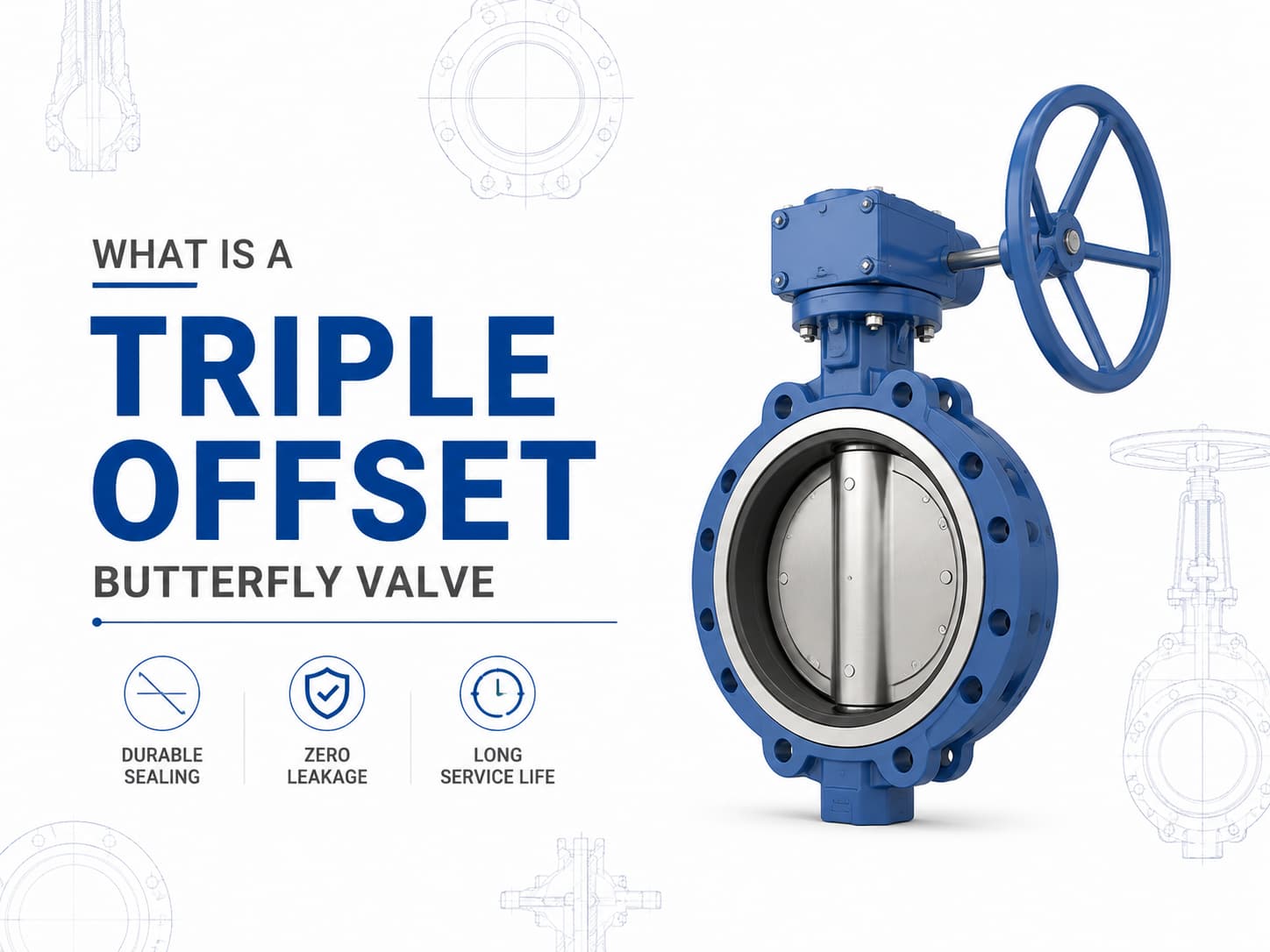
صمام فراشة ثلاثي الانحراف هو صمام عزل عالي الأداء مصمم للتطبيقات التي لا تستطيع فيها صمامات الفراشة التقليدية ذات المقعد المرن أو ذات الانحراف المزدوج تلبية متطلبات الضغط أو درجة الحرارة أو التسرب. وباستخدام تصميم إحكام ثلاثي الانحراف، يحقق الصمام آلية إحكام معدن-إلى-معدن مع تقليل الاحتكاك بين القرص والمقعد أثناء التشغيل، مما يجعله مناسبًا للخدمات الصعبة مثل النفط والغاز والبتروكيماويات وتوليد الطاقة والغاز الطبيعي المسال والبخار وأنظمة العمليات الصناعية. تصميم ومبدأ عمل صمام الفراشة ثلاثي الانحراف على عكس صمام الفراشة متحد المركز، حيث يتم وضع العمود على خط المنتصف للقرص والمقعد، فإن صمام الفراشة ثلاثي الانحراف يدمج ثلاثة انحرافات هندسية مستقلة. ينقل الانحراف الأول العمود بعيدًا عن خط المنتصف لجسم الصمام، بينما يزيح الانحراف الثاني العمود عن خط منتصف خط الأنابيب، ويضيف الانحراف الثالث سطح إحكام مخروطيًا بدلًا من شكل إحكام دائري. تسمح هذه الهندسة للقرص بالابتعاد عن المقعد مباشرة بعد بدء الدوران، مما يلغي الاحتكاك بين أسطح الإحكام. الميزة الرئيسية لهذا التصميم هي أن قوة الإحكام تتولد بواسطة عزم الدوران بدلًا من الضغط المستمر على المواد اللينة. إذا كان التطبيق يتطلب خدمة بدرجات حرارة عالية، فإن صمام الفراشة ثلاثي الانحراف ذو المقعد المعدني يُفضل غالبًا لأن مقاعد المطاط الصناعي قد تتدهور تحت درجات الحرارة المرتفعة. وإذا كان الوسط يحتوي على جسيمات كاشطة أو مواد كيميائية عدوانية، فإن اختيار مواد القرص والمقعد والجسم يصبح أمرًا بالغ الأهمية لمنع التآكل والتلف والتسرب أثناء التشغيل طويل الأمد. معايير ومواد صمام الفراشة ثلاثي الانحراف يُصنع صمام الفراشة ثلاثي الانحراف عادةً وفقًا لمعايير مثل API 609 وEN 593 وISO 5752، مع تصنيفات ضغط تتراوح من الفئة 150 إلى الفئة 600 وما فوق حسب متطلبات التصميم. تشمل المواد النموذجية الفولاذ الكربوني والفولاذ المقاوم للصدأ والفولاذ المقاوم للصدأ المزدوج وبرونز الألومنيوم والسبائك القائمة على النيكل. بالنسبة لتطبيقات مياه البحر المسببة للتآكل، قد يتم اختيار سبائك برونز الألومنيوم مثل C95500 أو C95800، بينما قد تتطلب تطبيقات الخدمة الحامضية مواد متوافقة مع متطلبات NACE MR0175/ISO 15156. أداء إحكام صمام الفراشة ثلاثي الانحراف والتحكم في التسرب يعتمد أداء إحكام صمام الفراشة ثلاثي الانحراف على التفاعل بين حلقة الإحكام وتشطيب سطح المقعد وعزم التشغيل وتوافق المواد. وبما أن أسطح الإحكام تتلامس فقط عند موضع الإغلاق النهائي، فإن التآكل الميكانيكي ينخفض بشكل كبير مقارنة بتصميمات صمامات الفراشة التقليدية. إذا كان التسرب الصفري مطلوبًا للعزل الحرج، فيجب مراعاة تصميم الصمام وفئة الضغط ومعيار التسرب المطبق، مثل API 598 أو ISO 5208، أثناء تحديد المواصفات. تطبيقات صمام الفراشة ثلاثي الانحراف واعتبارات الاختيار في خطوط الأنابيب ذات الأقطار الكبيرة، غالبًا ما يتم اختيار صمامات الفراشة ثلاثية الانحراف كبديل لصمامات البوابة لأنها توفر بُعدًا أقصر من وجه إلى وجه ووزن تركيب أقل. ومع ذلك، يجب أن يعتمد اختيار الصمام على ظروف التشغيل وليس على الحجم فقط. إذا كان خط الأنابيب يتطلب تشغيلًا متكررًا أو مساحة تركيب محدودة أو قدرة إغلاق عند درجات حرارة عالية، فقد يوفر تصميم الانحراف الثلاثي مزايا. وإذا كانت الخدمة تتطلب التحكم بالخنق، فيلزم إجراء تقييم إضافي لخصائص التدفق وحجم المشغل، لأن صمامات الفراشة مُحسّنة عمومًا لتطبيقات العزل والت...

الصمام الأعمى الخطي (صمام النظارات) هو نوع من صمام البوابة الذي يقطع وسيط الغاز يدويًا أو كهربائيًا أو هوائيًا أو هيدروليكيًا. وهي مقسمة عمومًا إلى صمام كهربائي أعمى ، وصمام أعمى هيدروليكي ، وصمام مغلق بسدادة ، وصمام أعمى كهربائي مفتوح.
دفع:
30% when order confirmed, 70% before shipmentأصل المنتج:
Chinaاللون:
Customizationميناء الشحن:
Shanghai, Chinaالمهلة:
30~60 days Ex Works after order confirmationوصف المنتج
يستخدم الصمام الأعمى الخطي على نطاق واسع في نظام إدارة الغاز المتوسط للمؤسسات الصناعية والتعدين والبلديات وحماية البيئة وغيرها من الصناعات ، خاصة لقطع الغازات الضارة والسامة والقابلة للاشتعال. يعتبر الصمام الأعمى الخطي مناسبًا أيضًا لاستخدامه كلوحة عمياء لمحطة الأنبوب لتقصير وقت الصيانة أو تسهيل توصيل نظام خط الأنابيب الجديد.
سمات
1. هيكل جديد وخفيف الوزن وصغر الحجم وعملية مريحة وعمل سريع وأداء موثوق به ؛
2. الإغلاق الإيجابي المطلق ، عدم الحاجة إلى انتشار الأنابيب ، الختم غير متأثر بعدم محاذاة الأنابيب.
رسم تقنى _ رسم عن طريق الكمبيوتر

مواصفات الصمامات الخطية العمياء
| وصف |
معيار |
| مقاس |
DN 15 (1/2 بوصة) إلى DN 1200 (48 بوصة) |
| فئة الضغط |
ASME 150 # ، 300 # ، 600 # |
| مادة الجسم |
|
| لوحة النظارات |
ستانلس ستيل |
| ينبع |
ستانلس ستيل |
| البراغي |
خليط معدني |
| يا الخواتم |
فيتون ، بونا إن |
| درجة حرارة |
232 درجة مئوية / 450 درجة فهرنهايت |
| اتصال الأنابيب |
أبيض وأسود / RF |
| شهادة |
ASME ، DIN ، ISO ، PED |
المعايير الهندسية للخطوط العمياء للصمامات
| معيار ASME |
وصف |
| ب 16.5 |
شفة الأنابيب والتجهيزات ذات الحواف |
| ب 16.34 |
الصمامات - ذات حواف وملولبة ونهايات لحام |
| B31.1 |
أنابيب الطاقة |
| ASTM F1020 |
خط الصمامات العمياء للتطبيقات البحرية |
| كود ASME B&PV |
الوصف (رمز وعاء الغلاية والضغط) |
| القسم الثاني |
مادة |
| القسم الثامن |
قواعد بناء أوعية الضغط |
| القسم التاسع |
مؤهلات اللحام والنحاس |
| معيار API |
وصف |
| ASME 16.48.001 |
الفراغات الخط الصلب للتكرير |
| API 598 |
فحص الصمام واختباره |
| API 2217 |
مبادئ توجيهية للعمل في الأماكن المحصورة في صناعة البترول |
| آحرون |
وصف |
| ISO 9001 |
نظام ادارة الجودة |
| NACE MR0175 |
تكسير إجهاد الكبريتيد والتآكل الإجهادي |
إذا كنت مهتما في منتجاتنا و تريد أن تعرف المزيد من التفاصيل,يرجى ترك رسالة هنا وسوف نقوم بالرد عليك بأسرع ما يمكن.
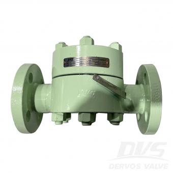
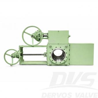
يتم استخدام الستائر الخطية في أنظمة خطوط الأنابيب عندما تكون هناك حاجة إما للإغلاق الكامل أو انتقال التدفق دون عوائق دون انخفاض كبير في الضغط. يتيح تصميم THD (التصميم من خلال الفتحة) إجراء تعديلات سريعة وسلسة في الموضع. يتميز متغير شريحة THD بتكوين متعدد البراغي، مما يجعل من السهل التشغيل بأبعاد منخفضة وجهاً لوجه. إن تضمين مسامير الجسم الإضافية يجعل هذا النمط مناسبًا بشكل خاص لتطبيقات الضغط العالي.
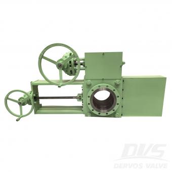
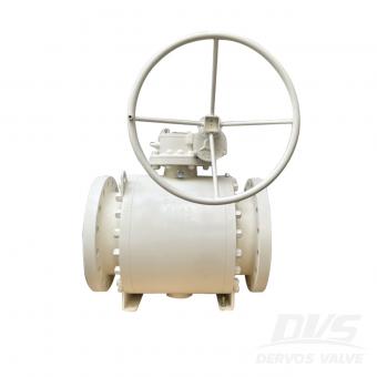
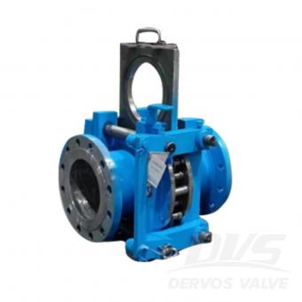
تم تصنيع الصمام الأعمى ذو الخط 10 بوصة 150LB وفقًا لمعيار ASME B16.34. جسم الصمام مصنوع من A105. له الخصائص الهيكلية المضادة للتنقيط. وضع الاتصال الخاص به هو RF. وله وضع تشغيل التوربين.
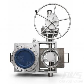
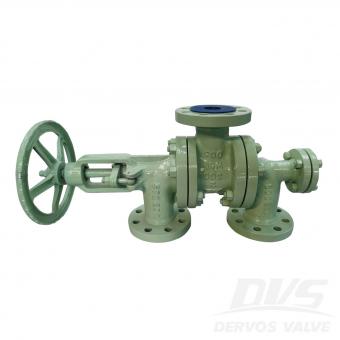
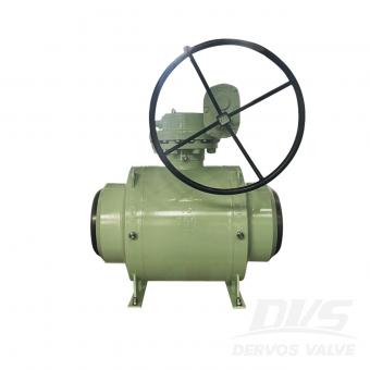
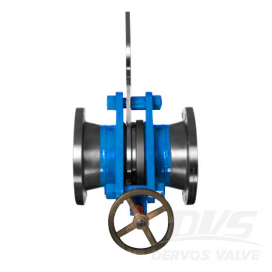
صمام DN400 PN40 المنزلق ذو الغطاء المغلق مصنوع وفقًا لمعيار EN12516-1/2. جسم الصمام مصنوع من الفولاذ LF2. صُمم الصمام للعمل مع البخار بدرجة حرارة تشغيل 250 درجة مئوية، وضغط تشغيل 1.3 ميجا باسكال، وضغط تصميم 2 ميجا باسكال، ونطاق درجة حرارة تصميم من -39 درجة مئوية إلى +350 درجة مئوية، ونطاق درجة حرارة محيطة من -39 درجة مئوية إلى +34.7 درجة مئوية. طريقة توصيله هي التردد اللاسلكي (RF). وهو مزود بتروس. وضع التشغيل. معايير المنتج يكتب صمام انزلاقي مغلق مقاس DN400 ضغط PN40 اتصال الترددات اللاسلكية عملية معدات مادة الجسم A182 LF2 معيار التصميم EN12516-1/2 وجهاً لوجه معايير الموردين أبعاد الشفة GOST 33259-النوع ب قانون الاختبار والتفتيش EN12266-1/2 درجة حرارة -29 ~ 120 درجة مئوية الوسيلة المناسبة الماء والنفط والغاز سمات 1. يوفر التصميم المصنوع من قطعة واحدة والمطروقة سلامة هيكلية عالية وأداءً مانعًا للتسرب تحت ضغط PN40. 2. آلية الانزلاق العمياء المزودة بشفة ترددات الراديو تسمح بعزل أجزاء خط الأنابيب بشكل آمن وفعال. الرسم الفني فحص الأبعاد اختبار الضغط تلوين لوحة الاسم والتغليف تقرير التفتيش
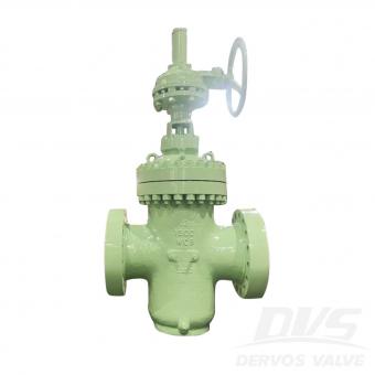
صمام انزلاقي مغلق بقطر 10 بوصات ووزن 150 رطلًا مصنوع وفقًا لمعيار ASME B16.34. جسم الصمام مصنوع من الألومنيوم A105. يتميز بتصميم مقاوم للتقطير. يعمل بنظام الترددات اللاسلكية (RF). مزود بتوربين. وضع التشغيل. معايير المنتج يكتب صمام انزلاقي مغلق مقاس 10 بوصات ضغط 150 رطل اتصال الترددات اللاسلكية عملية توربين مادة الجسم A105 معيار التصميم ASME B16.34 وجهاً لوجه معيار الشركة المصنعة أبعاد الشفة معيار ASME B16.5 قانون الاختبار والتفتيش API 598 درجة حرارة -29 ~ 150 درجة مئوية الوسيلة المناسبة الماء والنفط والغاز سمات 1. آلية الانزلاق التي تعمل بالتوربينات تتيح التشغيل السلس والفعال لعزل خطوط الأنابيب ذات الأقطار الكبيرة. 2. يضمن الهيكل المصنوع من الفولاذ الكربوني A105 المطروق مع شفة RF القوة والمتانة وأداء منع التسرب الموثوق به. الرسم الفني فحص الأبعاد اختبار الضغط تلوين لوحة الاسم والتغليف تقرير التفتيش
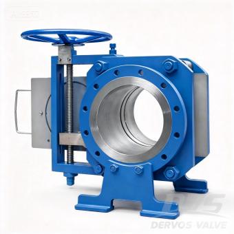
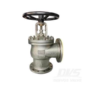
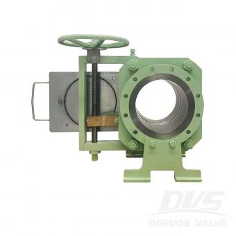
مقدمة يوفر صمام الخط المنزلق ذو الفئة 300 مقاس 10 بوصات عزلًا إيجابيًا مطلقًا لخطوط الأنابيب ذات الضغط المتوسط إلى العالي، حيث يجمع بين موثوقية الحاجز المادي الصلب وبساطة التشغيل اليدوي بواسطة البرغي. بخلاف الصمامات التقليدية التي تعتمد على مقاعد معرضة للتآكل، تُنشئ آلية الإغلاق المنزلقة حاجزًا ماديًا حقيقيًا، مما يضمن عدم حدوث أي تسريب أثناء الصيانة دون الحاجة إلى تخفيض ضغط النظام. وهذا يقلل بشكل كبير من وقت التوقف ويعزز سلامة العاملين. يوفر التصميم اليدوي الذي يعمل بالبرغي حركة دقيقة ومتحكم بها للوحة العمياء، مع قدرة القفل الذاتي المتأصلة للحفاظ على الوضع تحت الضغط - وهو مثالي للتطبيقات التي قد لا تتوفر فيها الطاقة الكهربائية أو الهوائية أو قد لا تكون مفضلة. صُمم هذا الصمام وفقًا لمعيار ASME B16.34 مع حواف RF وفقًا لمعيار ASME B16.5، وهو متوفر من الفولاذ الكربوني المطروق (A105) أو الفولاذ المقاوم للصدأ أو سبائك معدنية لتناسب ظروف التشغيل. تخضع كل وحدة لاختبار ضغط بنسبة 100% وفقًا لمعيار API 598. يُعد هذا التكوين ذو العشر بوصات من الفئة 300 خيارًا شائعًا لخطوط أنابيب البخار والنفط والغاز والمواد الكيميائية. تتوفر أحجام أخرى من بوصة واحدة إلى 60 بوصة وفئات ضغط تصل إلى الفئة 2500 ضمن سلسلة صماماتنا العمياء الكاملة. فتحة شريحة THD سمات 1. برغي يدوي التشغيل مع قفل ذاتي تتيح آلية التثبيت اللولبية الدقيقة وضع اللوحة العمياء بسلاسة وتحكم. وتحافظ آلية القفل الذاتي على الوضع تحت الضغط دون الحاجة إلى أجهزة كبح إضافية. 2. العزلة الجسدية المطلقة تُشكل الصفيحة العمياء الصلبة حاجزًا حقيقيًا، مما يضمن عدم حدوث أي تسرب أثناء الصيانة - على عكس الصمامات التي تعتمد على المقعد والتي يمكن أن تتآكل أو تتدهور بمرور الوقت. 3. التشغيل المباشر بدون تخفيف الضغط تتيح آلية الانزلاق التبديل بين وضعيات التدفق والوضعيات المغلقة دون الحاجة إلى تفريغ النظام، مما يقلل من وقت التوقف وفقدان المنتج. 4.10 بوصة الفئة 300 - التوازن الأمثل يوفر قدرة ضغط أعلى من الفئة 150 مع كونه أكثر اقتصادية من الفئة 600، مما يجعله خيارًا متعدد الاستخدامات لمجموعة واسعة من التطبيقات الصناعية. 5. هيكل من الفولاذ الكربوني المطروق يوفر الهيكل المصنوع من سبيكة A105 قوة عالية ومقاومة للصدمات وأداءً موثوقًا به في ظل دورات التغير الحراري. 6. تم اختباره وفقًا لمعيار API 598 يضمن الاختبار الهيدروستاتيكي والهوائي بنسبة 100% أداءً محكمًا ضد التسرب قبل الشحن. المواصفات القياسية المعلمة مواصفة يكتب صمام خطي منزلق مقاس 10 بوصة (DN250) تصنيف الضغط الفئة 300 (PN50) اتصال شفة الترددات الراديوية، ASME B16.5 عملية يدوي التشغيل بالبرغي (قفل ذاتي) مادة الجسم فولاذ كربوني مطروق A105 (تتوفر سبائك أخرى) مادة الختم / المقعد معدن إلى معدن (الفولاذ المقاوم للصدأ + الجرافيت) معيار التصميم ASME B16.34 البعد وجهاً لوجه وفقًا لمعيار ASME B16.10 أو معيار الشركة المصنعة الاختبار والفحص API 598 (هيدروستاتيكي وهوائي بنسبة 100%) نطاق درجة الحرارة من -29 درجة مئوية إلى +425 درجة مئوية (حسب نوع الختم) الوسائط المطبقة البخار، النفط، الغاز، الماء، الهيدروكربونات طلب عزل خطوط الأنابيب، مصافي النفط، مصانع البتروكيماويات، توليد الطاقة الرسم الفني خيارات تصميم مرنة تكوينات مصممة �


حقوق النشر © 2015-2026 DERVOS VALVE CO.,LTD.كل الحقوق محفوظة مدونة / خريطة الموقع / XML / سياسة الخصوصية