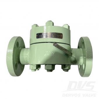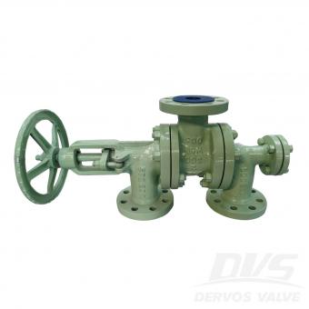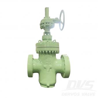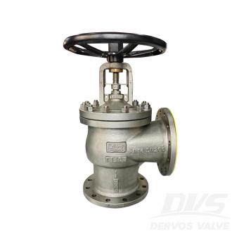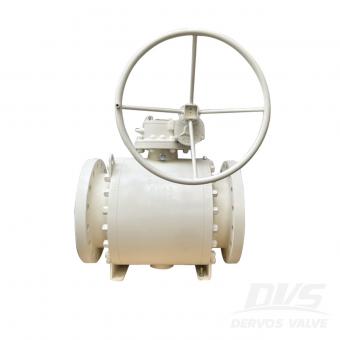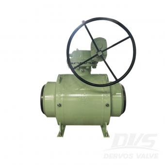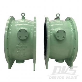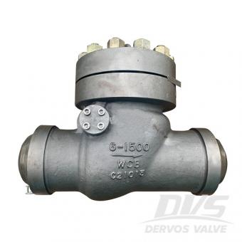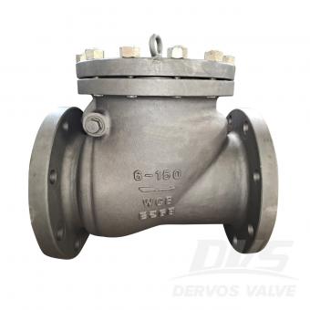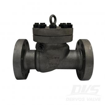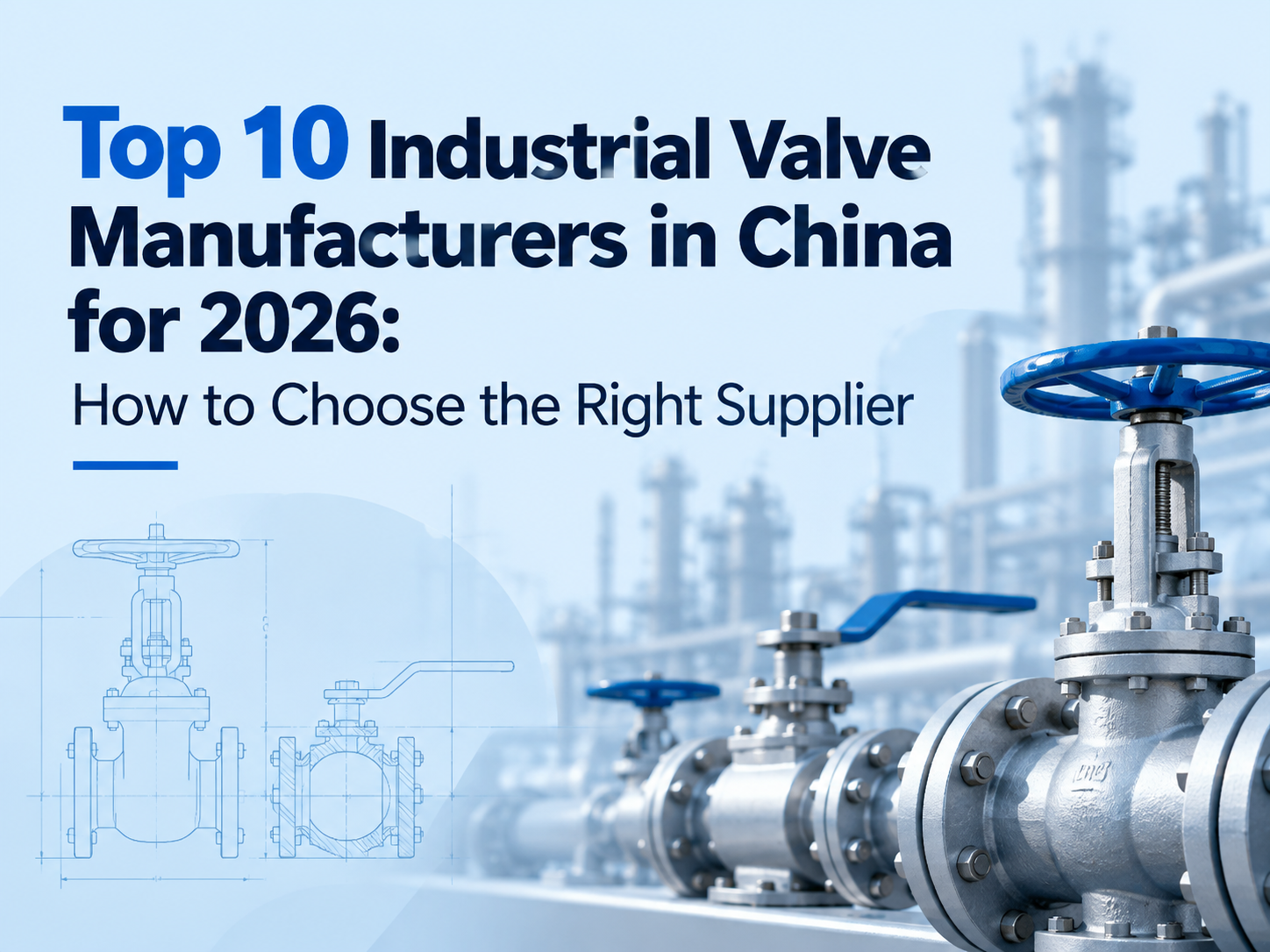
1. Suzhou Neway Valve Co., Ltd. — NEWAY NEWAY is one of China's most internationally recognized industrial valve manufacturers. Its product range includes ball valves, gate valves, globe valves, check valves, butterfly valves, cryogenic valves, subsea valves, and other engineered valve solutions. The company has strong experience in oil and gas, LNG, petrochemical, offshore, and power applications. Best suited for: large-scale energy projects and severe-service applications. 2. CNNC Sufa Technology Industry Co., Ltd. CNNC SUFA is well known for its experience in nuclear power and other high-integrity industrial applications. The company has strong capabilities in material traceability, engineering control, testing, and specialized valve manufacturing. Its products are also used in petroleum, petrochemical, power, and chemical industries. Best suited for: nuclear power, high-integrity systems, and technically demanding projects. 3. DERVOS VALVE DERVOS VALVE supplies industrial valves to customers in oil and gas, petrochemical, power generation, water treatment, marine, and general industrial applications. Its main products include ball valves, gate valves, globe valves, check valves, butterfly valves, plug valves, knife gate valves, line blind valves, and strainers. DERVOS supports international standards such as API, ASME, EN, and DIN, and can provide carbon steel, stainless steel, alloy steel, duplex stainless steel, low-temperature steel, and other materials. One of its key strengths is flexibility. DERVOS can support mixed valve packages, small-to-medium quantities, customized specifications, and project-specific documentation. Best suited for: overseas distributors, EPC projects, customized valves, mixed orders, and flexible sourcing requirements. 4. Yuanda Valve Group Yuanda Valve Group is one of China's large-scale valve manufacturers with broad production capacity. Its product range includes gate valves, globe valves, check valves, butterfly valves, ball valves, and other general industrial valves. The company is widely involved in water supply, HVAC, municipal infrastructure, power, and industrial pipeline projects. Best suited for: large-volume standardized valve procurement and general industrial applications. 5. Jiangsu Shentong Valve Co., Ltd. Jiangsu Shentong focuses strongly on specialized valve applications in metallurgy, energy, nuclear power, and chemical industries. Its strength lies in engineered products for demanding operating conditions rather than only standard valve production. Best suited for: metallurgy, energy, chemical processing, and specialized industrial applications. 6. Chaoda Valves Group Co., Ltd. Chaoda Valves Group serves petroleum, chemical, natural gas, power, and other process industries. Its product range includes ball valves, gate valves, globe valves, check valves, butterfly valves, and special-purpose industrial valves. The company has experience with corro...
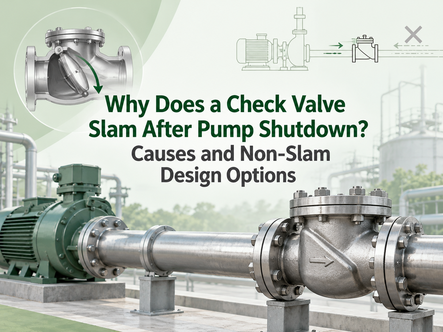
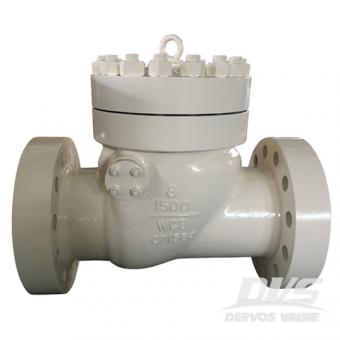
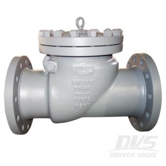
A check valve slams after pump shutdown when flow reverses before the closure member reaches its seat. The valve then stops that reverse velocity abruptly, creating a pressure wave through the piping. The damaging event is usually the rapid arrest of the liquid column, not simply the disc hitting the seat. A “non-slam” label alone is not a solution; the valve response must suit the system's flow deceleration. The Valve Is Closing Too Late for the Shutdown Transient When pump torque disappears, forward velocity falls. Static head, a pressurised common header or another running pump may then drive liquid back toward the stopped pump. If inertia and hinge friction keep a conventional swing disc open through zero flow, reverse velocity develops before the disc reaches its seat. High static lift, a steep rising main, short pump coast-down, parallel pumps and high initial velocity can accelerate this reversal. A long-stroke or high-inertia valve is more likely to lag. This is why the same valve may run quietly in one system and slam in another: nominal size and pressure class do not define shutdown behaviour. Confirm the Event Before Changing the Valve A single hard bang after shutdown points toward check-valve closure or another surge event. Continuous clicking during forward flow is chatter, which more often indicates unstable partial opening, pulsation or poor hydraulic sizing. Record the stop command, motor speed decay, flow direction and pressures on both sides of the valve on a common time base. A high-speed video of an external lever or position indicator can help show when the valve closes. For consequential systems, fast pressure logging is more reliable than sound alone. Inspect the hinge, shaft, spring and seat for friction, wear, deposits or damage, and verify the permitted installation orientation. Check pipe supports as well; the pressure wave may produce its loudest noise away from the valve. Non-Slam Designs Use Different Closing Strategies An axial-flow or nozzle check valve uses a light, centrally guided disc, short travel and spring assistance. It begins closing as forward flow falls, ideally seating before appreciable reversal. It is a strong candidate for rapid pump trips, but pressure loss, cracking pressure, minimum stable flow, orientation and tolerance of solids still matter. A spring-assisted dual-plate valve uses two lighter plates and shorter travel than a conventional swing disc. Its compact construction can improve response, but “dual plate” does not mean slam-free. Plate inertia, spring torque, size and mounting position remain relevant. Tilting-disc, resilient-hinge and spring-assisted swing designs reduce travel or assist closure while retaining a relatively open flow path. They can suit large water lines where energy loss matters, provided dynamic data supports the selected design and size. Large pumping mains ma...
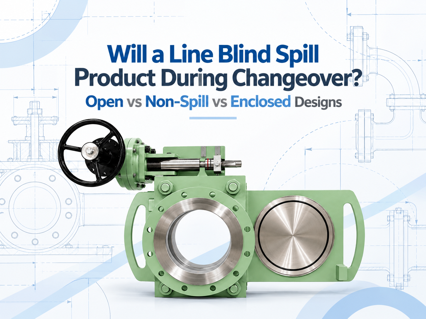
نعم، يمكن لستارة الأنابيب ذات الهيكل المفتوح أن تطلق منتجًا متبقيًا عندما تتغير بين الوضعين المفتوح والمسدود. والتصميم المانع للانسكاب لا يجعل تلك بقايا تختفي؛ بل يلتقط السائل في حاوية جزئية ويوجهه إلى تصريف. يمكن للتصميم المغلق أن يوفر تحكمًا أفضل في السائل والبخار، ولكن فقط عندما تكون وصلات الهيكل والتصريف والتفريغ والتطهير مصممة خصيصًا لهذه الخدمة. لا ينبغي قراءة أي من هذه التسميات كتصريح بتحريك الستارة تحت ضغط الخط الحي. لماذا يمكن للمنتج أن يتسرب أثناء التغيير عندما تكون ستارة الأنابيب مثبتة بالكامل، فإن أختامها تحتفظ بالعملية وتوفر اللوحة الصلبة عزلاً إيجابيًا في وضع الانسداد. عملية التغيير مختلفة. يجب أن تنفصل أسطح مانع التسرب قبل أن تتمكن لوحة النظارة أو اللوحة الانزلاقية من الحركة. خلال تلك الفترة، قد تكون تجويف الهيكل ومسار اللوحة مفتوحين للمنطقة المحيطة. يجب أن يكون الخط معزولاً ومفرغاً من الضغط ومصرفاً بالفعل، ولكن كلمة "مصرف" نادراً ما تعني جافاً تماماً. يمكن أن يظل السائل كغشاء على اللوحة، أو يتجمع في الجزء السفلي من الهيكل، أو يستقر في جيب أنبوب سيئ التصريف. قد تترك خدمة الغاز بخارًا قابلاً للاشتعال أو سامًا أو كريه الرائحة. لذلك، تعتمد الكمية المنطلقة على تخطيط الأنابيب وإجراءات إيقاف التشغيل بقدر ما تعتمد على ستارة الأنابيب نفسها. التصاميم الثلاثة تتعامل مع البقايا بطرق مختلفة التصميم ذو الهيكل المفتوح يمكن للسائل المتبقي أن يقطر من مسار اللوحة المكشوفة إلى صينية مؤقتة أو منطقة العمل، بينما يتشتت البخار محليًا. يمكن أن يناسب هذا الترتيب الماء، أو متكثف البخار، أو الوسائط الأخرى التي يمكن التعامل معها حيث يهم الوصول السهل و الفحص البصري. إنه يقدم أعلى إمكانية لتلوث الأرضية وتعرض المشغل. التصميم المانع للانسكاب يلتقط الغطاء السفلي والجانبي قطرات السائل ويرسلها إلى تصريف أو حاوية استعادة؛ وقد يظل الجزء العلوي مفتوحًا. يُعتبر هذا التصميم شائع الاستخدام في محطات الوقود، والخدمات البحرية، ومهام السوائل حيث يجب التحكم في تلوث الأرض أو السطح. إنه يقلل من التنقيط ولكنه قد لا يحتوي البخار، والتصريف المسدود يبطل غرضه. التصميم المغلق يحيط غلاف بأغلب أو كل مسار حركة اللوحة وقد يتصل بنظام تصريف مغلق أو تطهير أو تفريغ أو شعلة أو نظام استعادة البخار. إنه مناسب بشكل أفضل للخدمات السامة أو القابلة للاشتعال أو كريهة الرائحة أو الحساسة بيئيًا التي تتطلب احتواءً محكومًا. المبادلة هي التعقيد الأكبر في التطهير والفحص والصيانة، إلى جانب الحاجة إلى إدارة الضغط المحتجز بشكل متعمد. هذه الأسماء ليست موحدة تمامًا عبر الشركات المصنعة. قد يكون طراز "المانع للانسكاب" لأحد الموردين مفتوحًا من الأعلى، بينما قد يستخدم منتج آخر موصوف بأنه مغلق غلافًا أكثر اكتمالاً. يجب أن يوضح طلب العرض ترتيب الغلاف وأن يحدد كل فتحة بدلاً من الاعتماد على اسم المنتج. المنع من الانسكاب لا يعني تلقائيًا التسريب الصفري بالنسبة لسائل ذي تطاير منخفض، قد يكون التقاط القطرات المتبقية وتوجيهها إلى حاوية مغلقة كافياً. يخلق الهيدروكربون المتطاير مشكلة مختلفة: قد يتم التقاط السائل بينما يظل البخار يخرج من خلال فتحة علوية أو مهواة مفتوحة. تتطلب خدمة الغاز السام التحكم في كل من السائل المرئي ومسار التسريب غير المرئي. يجب أيضًا فهم الغلاف بشكل صحيح. بعض الهياكل هي أغطية تجميع وليست حدودًا ثانوية مصنفة للضغط. إذا كان من الممكن عزل تجويف أثناء احتوائه على سائل، فقد تؤدي ...


حقوق النشر © 2015-2026 DERVOS VALVE CO.,LTD.كل الحقوق محفوظة مدونة / خريطة الموقع / XML / سياسة الخصوصية