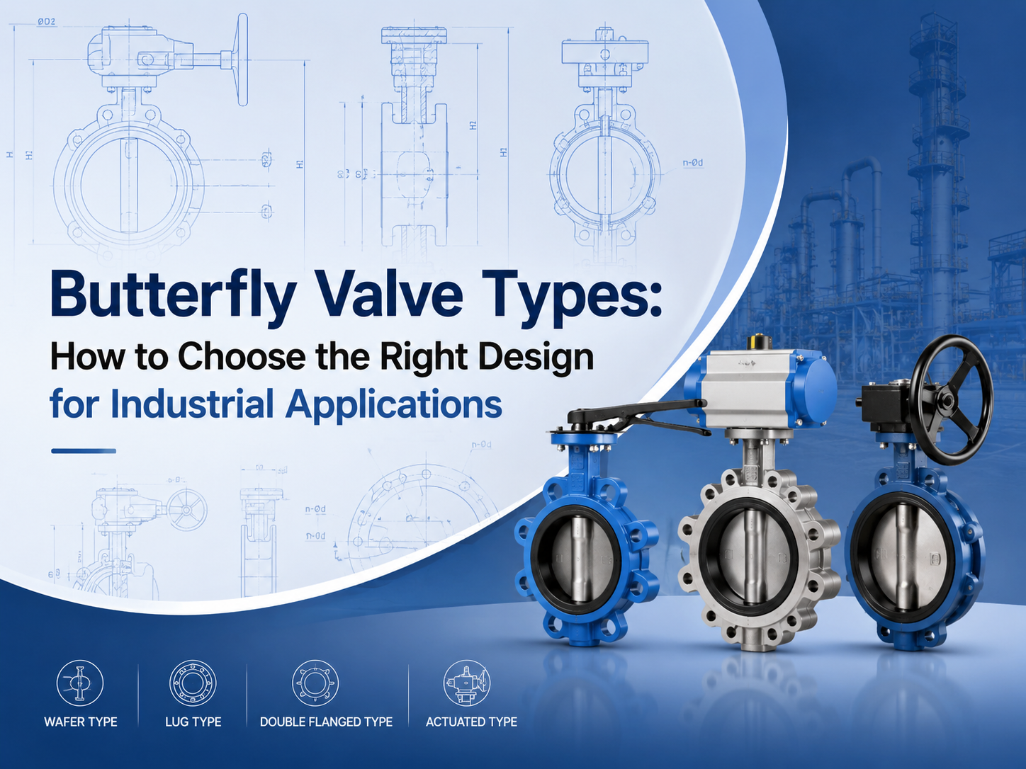
تشمل الأنواع الرئيسية لصمامات الفراشة الصمام متحدة المركز، والصمام مزدوج الإزاحة، والصمام ثلاثي الإزاحة، والصمام الرقائقي، والصمام ذو العروات، والصمام ذو الحواف، والصمام ذو المقعد المرن، والصمام ذو المقعد المعدني، والصمام اليدوي، والصمام الهوائي، وصمام الفراشة الكهربائي. يعتمد الاختيار الصحيح على الضغط ودرجة الحرارة والوسيط ومتطلبات التسرب ومساحة التركيب وتكرار التشغيل. ما هي الأنواع الرئيسية لصمامات الفراشة؟ تُصنَّف صمامات الفراشة عادةً حسب تصميم القرص، وطريقة توصيل الجسم، ومادة المقعد، وطريقة التشغيل. هذا التصنيف مهم لأن صمامين قد يُسمَّيان كلاهما صمامات فراشة، لكن حدود الخدمة الخاصة بهما قد تكون مختلفة جدًا. يستخدم صمام الفراشة قرصًا دوارًا لعزل التدفق أو تنظيمه. وبفضل هيكله المدمج ووزنه الخفيف وتشغيله بربع دورة، يُستخدم على نطاق واسع في معالجة المياه ومحطات الطاقة والمعالجة الكيميائية وأنظمة التدفئة والتهوية وتكييف الهواء والأنظمة البحرية وخطوط الأنابيب الصناعية العامة. بالنسبة للمشترين، لا يتمثل السؤال الرئيسي ببساطة في «أي نوع أرخص؟» بل في «أي نوع يمكنه تحمل الضغط ودرجة الحرارة والوسيط ومتطلبات الإحكام الفعلية؟» صمام الفراشة متحد المركز A صمام فراشة متحد المركزيكون ساقه موجودًا على خط المنتصف لجسم الصمام والقرص. ويُسمى أيضًا صمام الفراشة المحوري. يُستخدم هذا النوع عادةً في تطبيقات الضغط المنخفض والخدمات العامة، خاصةً مع الماء والهواء والسوائل غير العدوانية. وهو بسيط واقتصادي وسهل الصيانة. يتمثل القيد في تآكل المقعد. أثناء الفتح والإغلاق، يبقى القرص ملامسًا للمقعد المرن خلال جزء كبير من حركته. بالنسبة للضغط الأعلى أو درجة الحرارة الأعلى أو متطلبات الإغلاق الأكثر صرامة، تكون تصاميم الإزاحة المزدوجة أو الثلاثية غالبًا أكثر ملاءمة. صمام الفراشة مزدوج الإزاحة A صمام فراشة مزدوج الإزاحةيستخدم إزاحتين لتقليل الاحتكاك بين القرص والمقعد. وهذا يحسن أداء الإحكام ويساعد على إطالة عمر الخدمة مقارنةً بالتصميم متحد المركز الأساسي. غالبًا ما يتم اختيار صمامات الفراشة مزدوجة الإزاحة لخدمات الضغط المتوسط الصناعية، بما في ذلك النفط والغاز وإمدادات المياه وتوليد الطاقة والأنظمة الكيميائية. وهي مفيدة عندما يحتاج التطبيق إلى متانة أفضل ولكنه لا يتطلب تصميمًا كاملًا ثلاثي الإزاحة بمقعد معدني. يُسمى هذا النوع أيضًا بشكل شائع صمام الفراشة عالي الأداء. قبل الاختيار، يجب على المشترين التأكد من فئة الضغط ومادة المقعد وتصميم إحكام العمود وتكرار التشغيل المتوقع. صمام الفراشة ثلاثي الإزاحة A صمام فراشة ثلاثي الإزاحةيضيف إزاحة هندسية ثالثة لإنشاء هيكل إحكام أكثر تقدمًا. ويُستخدم عادةً في تطبيقات درجات الحرارة العالية والضغط العالي أو الخدمات القاسية. يقلل التصميم الاحتكاك بين أسطح الإحكام أثناء التشغيل. تستخدم العديد من صمامات الفراشة ثلاثية الإزاحة مقاعد معدنية، مما يجعلها مناسبة للبخار والنفط والغاز والمواد الكيميائية وغيرها من الأوساط الصعبة. بالنسبة لهذه التطبيقات، تعد المعايير والاختبارات مهمة. غالبًا ما يحتاج المشترون إلى التحقق مما إذا كان تصميم الصمام يتبع معايير مثل API 609 وEN 593 وISO 5752 وASME B16.34 أو API 598، وفقًا لمتطلبات المشروع. صمامات الفراشة الرقاقية وذات العروات وذات الحواف يؤثر اتصال الجسم على التركيب والصيانة. النوع الأفضل لـ النقطة الرئيسية صمام فراشة رقائقي أنظمة الأنابيب المدمجة يُثبت بين حافتين صمام فراشة ذو عرو...
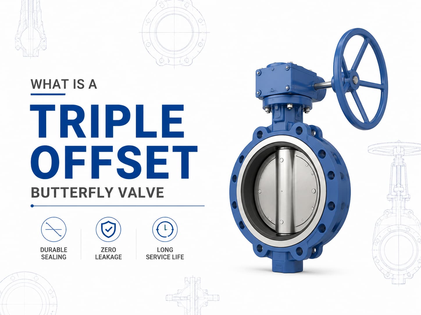
صمام فراشة ثلاثي الانحراف هو صمام عزل عالي الأداء مصمم للتطبيقات التي لا تستطيع فيها صمامات الفراشة التقليدية ذات المقعد المرن أو ذات الانحراف المزدوج تلبية متطلبات الضغط أو درجة الحرارة أو التسرب. وباستخدام تصميم إحكام ثلاثي الانحراف، يحقق الصمام آلية إحكام معدن-إلى-معدن مع تقليل الاحتكاك بين القرص والمقعد أثناء التشغيل، مما يجعله مناسبًا للخدمات الصعبة مثل النفط والغاز والبتروكيماويات وتوليد الطاقة والغاز الطبيعي المسال والبخار وأنظمة العمليات الصناعية. تصميم ومبدأ عمل صمام الفراشة ثلاثي الانحراف على عكس صمام الفراشة متحد المركز، حيث يتم وضع العمود على خط المنتصف للقرص والمقعد، فإن صمام الفراشة ثلاثي الانحراف يدمج ثلاثة انحرافات هندسية مستقلة. ينقل الانحراف الأول العمود بعيدًا عن خط المنتصف لجسم الصمام، بينما يزيح الانحراف الثاني العمود عن خط منتصف خط الأنابيب، ويضيف الانحراف الثالث سطح إحكام مخروطيًا بدلًا من شكل إحكام دائري. تسمح هذه الهندسة للقرص بالابتعاد عن المقعد مباشرة بعد بدء الدوران، مما يلغي الاحتكاك بين أسطح الإحكام. الميزة الرئيسية لهذا التصميم هي أن قوة الإحكام تتولد بواسطة عزم الدوران بدلًا من الضغط المستمر على المواد اللينة. إذا كان التطبيق يتطلب خدمة بدرجات حرارة عالية، فإن صمام الفراشة ثلاثي الانحراف ذو المقعد المعدني يُفضل غالبًا لأن مقاعد المطاط الصناعي قد تتدهور تحت درجات الحرارة المرتفعة. وإذا كان الوسط يحتوي على جسيمات كاشطة أو مواد كيميائية عدوانية، فإن اختيار مواد القرص والمقعد والجسم يصبح أمرًا بالغ الأهمية لمنع التآكل والتلف والتسرب أثناء التشغيل طويل الأمد. معايير ومواد صمام الفراشة ثلاثي الانحراف يُصنع صمام الفراشة ثلاثي الانحراف عادةً وفقًا لمعايير مثل API 609 وEN 593 وISO 5752، مع تصنيفات ضغط تتراوح من الفئة 150 إلى الفئة 600 وما فوق حسب متطلبات التصميم. تشمل المواد النموذجية الفولاذ الكربوني والفولاذ المقاوم للصدأ والفولاذ المقاوم للصدأ المزدوج وبرونز الألومنيوم والسبائك القائمة على النيكل. بالنسبة لتطبيقات مياه البحر المسببة للتآكل، قد يتم اختيار سبائك برونز الألومنيوم مثل C95500 أو C95800، بينما قد تتطلب تطبيقات الخدمة الحامضية مواد متوافقة مع متطلبات NACE MR0175/ISO 15156. أداء إحكام صمام الفراشة ثلاثي الانحراف والتحكم في التسرب يعتمد أداء إحكام صمام الفراشة ثلاثي الانحراف على التفاعل بين حلقة الإحكام وتشطيب سطح المقعد وعزم التشغيل وتوافق المواد. وبما أن أسطح الإحكام تتلامس فقط عند موضع الإغلاق النهائي، فإن التآكل الميكانيكي ينخفض بشكل كبير مقارنة بتصميمات صمامات الفراشة التقليدية. إذا كان التسرب الصفري مطلوبًا للعزل الحرج، فيجب مراعاة تصميم الصمام وفئة الضغط ومعيار التسرب المطبق، مثل API 598 أو ISO 5208، أثناء تحديد المواصفات. تطبيقات صمام الفراشة ثلاثي الانحراف واعتبارات الاختيار في خطوط الأنابيب ذات الأقطار الكبيرة، غالبًا ما يتم اختيار صمامات الفراشة ثلاثية الانحراف كبديل لصمامات البوابة لأنها توفر بُعدًا أقصر من وجه إلى وجه ووزن تركيب أقل. ومع ذلك، يجب أن يعتمد اختيار الصمام على ظروف التشغيل وليس على الحجم فقط. إذا كان خط الأنابيب يتطلب تشغيلًا متكررًا أو مساحة تركيب محدودة أو قدرة إغلاق عند درجات حرارة عالية، فقد يوفر تصميم الانحراف الثلاثي مزايا. وإذا كانت الخدمة تتطلب التحكم بالخنق، فيلزم إجراء تقييم إضافي لخصائص التدفق وحجم المشغل، لأن صمامات الفراشة مُحسّنة عمومًا لتطبيقات العزل والت...
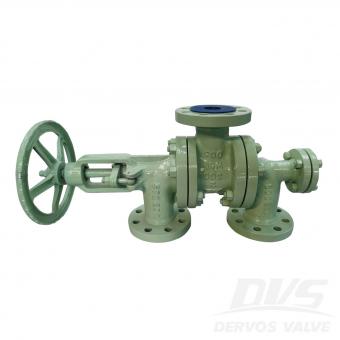
تُعد صمامات الكرة والصمامات السدّادية كلاهما صمامات دوارة ربع دورة تُستخدم للتحكم في التشغيل والإيقاف والعزل في أنظمة الأنابيب الصناعية. وعلى الرغم من أنها تشترك في مبادئ تشغيل متشابهة، فإن تصاميمها الداخلية تؤدي إلى خصائص أداء مختلفة، خاصة من حيث الإحكام، وقدرة تحمل الضغط، وعزم التشغيل، ومتطلبات الصيانة، ومدى ملاءمتها للوسائط المختلفة. يجب أن يعتمد الاختيار بين الصمام الكروي والصمام السدّادي على ظروف التشغيل الفعلية بدلًا من تفضيل نوع الصمام. إذا كان التطبيق يتطلب إغلاقًا محكمًا، وتشغيلًا متكررًا، وعزم تشغيل منخفضًا، فغالبًا ما يُفضّل الصمام الكروي. وإذا كان النظام يتعامل مع وسائط متسخة أو جزيئات كاشطة أو ممرات تدفق كبيرة، فقد يوفر الصمام السدّادي موثوقية أفضل. اختلافات التصميم وأداء الإحكام أحد صمام كروييستخدم عنصر إغلاق كروي الشكل مزودًا بثقب محفور. عندما يكون الصمام مفتوحًا، يتماشى الثقب مع خط الأنابيب لتوفير مسار تدفق شبه غير مقيد. وعند تدويره بزاوية 90 درجة، يحجب الجزء المصمت من الكرة الممر ويوفر الإغلاق. يستخدم الصمام السدّادي سدادة أسطوانية أو مخروطية تحتوي على ممر تدفق عبر المركز. تدور السدادة داخل الجسم للتحكم في التدفق. وبحسب التصميم، يمكن أن تكون الصمامات السدّادية مُزلّقة أو ذات بطانة أو غير مُزلّقة، حيث يوفر كل هيكل خصائص إحكام مختلفة. تُعد آلية الإحكام إحدى الاختلافات الرئيسية بين الصمامين. تستخدم الصمامات الكروية عمومًا مقاعد لينة أو مقاعد معدنية أو مزيجًا من كليهما لتحقيق إغلاق موثوق. إذا كان النظام يتطلب عزلًا محكمًا دون فقاعات، خاصة في خدمة الغاز أو تطبيقات العمليات الحرجة، فإن الصمام الكروي المختار بشكل صحيح يمكن أن يوفر أداء إحكام ممتازًا. تعتمد الصمامات السدّادية على التلامس بين السدادة وجسم الصمام أو البطانة. تستخدم الصمامات السدّادية المُزلّقة مادة مانعة للتسرب تُحقن بين السدادة والجسم لتقليل الاحتكاك وتحسين الإحكام. يمكن لهذا التصميم أن يعمل جيدًا في التطبيقات التي تحتوي فيها الوسائط على ملوثات، لأن مادة الإحكام تساعد على حماية أسطح الإغلاق. اعتبارات التطبيق تحدد ظروف التشغيل ما إذا كان الصمام الكروي أو الصمام السدّاديهو الأكثر ملاءمة. تُستخدم الصمامات الكروية على نطاق واسع في صناعات النفط والغاز والبتروكيماويات والغاز الطبيعي المسال والمعالجة الكيميائية والطاقة حيث يكون الإغلاق الموثوق مطلوبًا. تُستخدم الصمامات الكروية العائمة عادةً في أنظمة الضغط المنخفض، بينما تُفضّل الصمامات الكروية المركبة على مرتكزات الدوران للأحجام الأكبر وتصنيفات الضغط الأعلى لأن دعم مرتكز الدوران يقلل عزم التشغيل. إذا كان الصمام سيتعرض لدورات تشغيل متكررة، فإن الصمام الكروي يوفر عادةً ميزة بسبب تشغيله منخفض الاحتكاك وتفعيله بربع دورة. ومع ذلك، يلزم إجراء دراسة دقيقة عند التعامل مع سوائل تحتوي على جزيئات صلبة. إذا علقت الجزيئات الكاشطة بين الكرة والمقعد، فقد يحدث تلف للمقعد وتسرب. غالبًا ما يتم اختيار الصمامات السدّادية للتطبيقات التي تتضمن سوائل متسخة، ومعلقات، ومياه صرف، وخطوط الأنابيبحيث قد تحتوي وسائط التدفق على مواد صلبة عالقة. يقلل ممر التدفق الكبير والمستقيم من خطر الانسداد. إذا كان مائع العملية يحتوي على ملوثات قد تتسبب في تلف مواد الإحكام اللينة، فقد يوفر الصمام السدّادي ذو المقعد المعدني أو المُزلّق أداء خدمة أفضل. تُعد درجة الحرارة والضغط أيضًا من العوامل المهمة. إذا كان التطبيق يتضمن ضغطًا مرتفعًا أو درجة حرار...
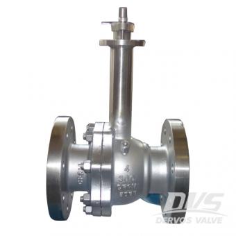
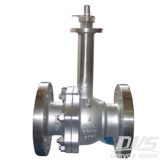
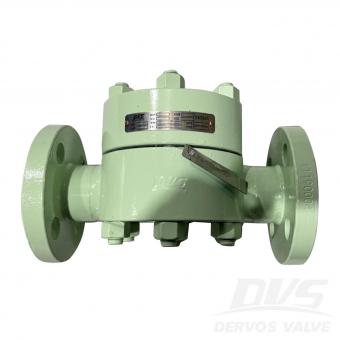
يحتوي الصمام الكروي المبرد 4 بوصة ، المصمم وفقًا لـ api609 ، على العديد من الأجزاء المجهزة rptfe - ولديه أقل معامل الاحتكاك وأفضل مقاومة للتآكل لأي مادة بلاستيكية معروفة ، بحيث يمكن للصمام التعامل مع المواقف القاسية تمامًا.
دفع:
30% T/T When Order, 70% T/T Before Shipmentأصل المنتج:
Chinaاللون:
Customizationميناء الشحن:
Shanghai, Chinaالمهلة:
30~60 days Ex Works after order confirmationMaterial:
F316Method of Operation:
Leverتفاصيل سريعة
|
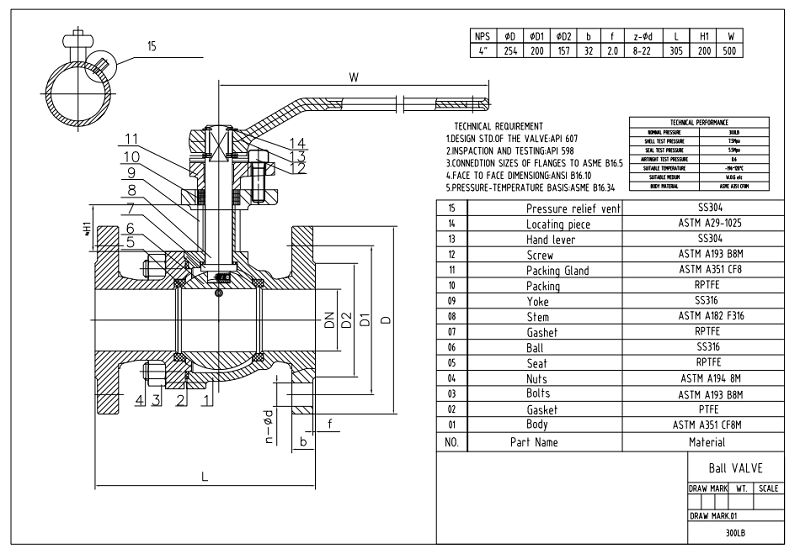
نوع |
صمام الكرة |
|
القطر الاسمي |
4 " |
|
الضغط الاسمي |
300 رطل |
|
اعمال بناء |
اللحام المسدود ، الجذع الممتد أو غطاء المحرك ، المنفذ الكامل |
|
الإتصال |
الترددات اللاسلكية |
|
عملية |
تعمل رافعة |
|
مواد الجسم |
ص 316 |
|
كود التصميم |
api 607 |
|
الضغط & أمبير ؛ مؤقت |
اسمي ب 16.34 |
|
البعد نهاية نهاية |
Asme b16.10 |
|
حجم اتصال الشفاه |
Asme b16.5 |
|
تفتيش |
api598 |
|
نطاق درجة حرارة |
-196 ℃ ~ + 120 ℃ |
|
وسائل الإعلام |
النفط والماء والغاز |
ميزة التصميم
تمديد الجذع وغطاء المحرك لوضع التعبئة الجذعية فوق السائل المبرد وتوفير عمود من البخار الدافئ الذي يعزل ختم الجذع من تأثيرات درجات الحرارة المنخفضة.
تتيح المقاعد والأختام عالية الكثافة في جميع أنحاء الصمام أن يتم تصنيف الصمام إلى درجة حرارة -196 درجة مئوية.
فتحة تنفيس في وجه الكرة المنبع. هذا يمنع السوائل الباردة من الوقوع في الصمام.
يقع ختم ومحمل الساق الأساسي بالقرب من نهاية تعبئة الجذع الممتد ، وبالتالي الحفاظ على هذه الأجزاء من درجات الحرارة المنخفضة وتوفير تصميم جذع مقاوم للانفجار.
يتم تنظيف الصمامات خصيصًا لإزالة جميع الشحوم والزيوت التي قد تتفاعل مع وسائط الخدمة
يتم تعبئة كل صمام بعد التنظيف وإغلاقه في كيس بولي ثقيل للحفاظ على الصمام نظيفًا حتى التثبيت.
رسم تقنى _ رسم عن طريق الكمبيوتر
خدمتنا
تعتبر خدمة عملاء dervos واحدة من أكبر مزايانا التنافسية. في dervos ، نحن نقدم-
1. الاقتباس في غضون 24 ساعة أو في موعد لا يتجاوز 3 أيام
سيتيح لك ذلك الوفاء بالموعد النهائي لتقديم عرض الأسعار وتحسين كفاءة عملك
2. تقرير الحالة الأسبوعية لطلبك
بهذه الطريقة ، سيكون لديك صورة واضحة لطلبك. لا تحتاج إلى إضاعة الوقت في دفعنا لتحديث الحالة
3. فترة ضمان 18 شهر
سيتم إصدار شهادة الضمان بعد الشحن ولن يكون لديك أي قلق بعد شراء الصمامات.
4. حلول للشكاوي خلال 3 أيام
الإجراءات السريعة والمسؤولة للشكاوى ستحمي سمعتك وتقلل من الخسائر المالية قدر الإمكان.
إذا كنت مهتما في منتجاتنا و تريد أن تعرف المزيد من التفاصيل,يرجى ترك رسالة هنا وسوف نقوم بالرد عليك بأسرع ما يمكن.
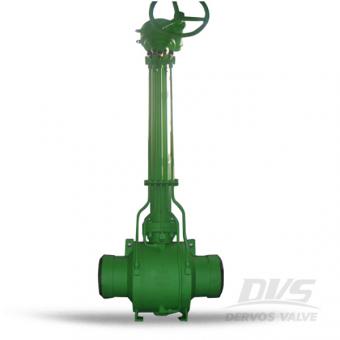
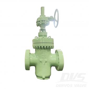
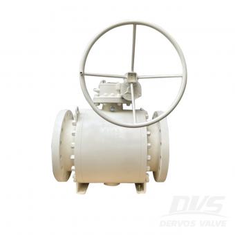
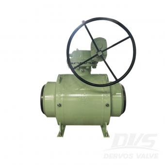
تم تصميم صمام الكرة المبردة فئة 1500 4 بوصة مع ساق ممتدة لتطبيق درجة حرارة منخفضة. الصمام مصنوع من lf2 بجسم ملحوم بالكامل ، ونهاية ملحومة بعقب وتشغيل علبة التروس. ميزة التصميم - ملحوم & أمبير ؛ هيئة مزورة - جذع أو غطاء محرك السيارة الممتد -تصميم منفذ كامل وخنزير -أنتي تفجير الجذعية دالة-استاتيكية - تخفيف التجويف التلقائي - مقعد ذو اتجاهين وتصميم ديسيبل ، مع تجهيزات شحم المقعد والمقعد تفاصيل سريعة نوع صمام الكرة بحجم 4 " الضغط انسي 1500 اعمال بناء جسم من قطعة واحدة ، اللحام الكامل ، الجذعية الممتدة أو غطاء المحرك ، منفذ كامل الإتصال بعقب اللحام عملية ناقل الحركة تعمل الجسم مواد درجة حرارة منخفضة الفولاذ A350 lf2 كود التصميم واجهة برمجة التطبيقات 6 د الضغط & أمبير ؛ مؤقت اسمي ب 16.34 البعد من النهاية إلى النهاية Asme b16.10 النهاية الإتصال أسمي ب 16.25 تفتيش api 598 درجة الحرارة نطاق -46 ℃ ~ + 200 ℃ وسائل الإعلام نفط، الماء والغاز المعرفة ذات الصلة ما هو الفرق بين التجويف الكامل وصمام التجويف المنخفض؟ القطر الداخلي لصمام كرة تتحمل كامل هو نفس القطر الداخلي للأنبوب. الصمام الكرة تتحمل كامل لديه القليل من المقاومة وانخفاض الضغط على التدفق. بالإضافة إلى ذلك ، صمام الكرة تتحمل كامل قابل للخنزير. ومع ذلك ، فإن القطر الداخلي لصمام الكرة المخفض (المنفذ القياسي) أصغر من حجم الأنبوب الداخلي. سيؤدي تقييد التدفق الناتج عن المنفذ المخفض إلى انخفاض الضغط. وأحيانًا يعلق خنزير لتنظيف الأنبوب في صمام الكرة المخفض. الشهادات يمكن لشركة Dervos تقديم تقارير بناءً على طلبات العملاء ، مثل iso 9001 و ped ce و eac و api 607 و api 6d و api 6a وما إلى ذلك.


حقوق النشر © 2015-2026 DERVOS VALVE CO.,LTD.كل الحقوق محفوظة مدونة / خريطة الموقع / XML / سياسة الخصوصية