Yes, an open-body line blind can release residual product when it changes between the open and blind positions. A non-spill design does not make that residue disappear; it catches the liquid in a partial enclosure and directs it to a drain. An enclosed design can provide better control of liquid and vapour, but only when its housing, drain, vent and purge connections are engineered for the service. None of these labels should be read as permission to move the blind under live line pressure. Why Product Can Escape During Changeover When a line blind is fully clamped, its seals contain the process and the solid plate provides positive isolation in the blind position. Changeover is different. The sealing faces must separate before the spectacle or sliding plate can move. During that interval, the body cavity and plate path may be open to the surrounding area. The line should already be isolated, depressurised and drained, but “drained” rarely means perfectly dry. Liquid can remain as a film on the plate, collect in the lower body, or sit in a poorly drained pipe pocket. Gas service may leave flammable, toxic or odorous vapour. The amount released therefore depends as much on piping layout and the shutdown procedure as on the line blind itself. The Three Designs Manage Residue Differently Open-body design Residual liquid can drip from the exposed plate path into a temporary tray or the work area, while vapour disperses locally. This arrangement can suit water, steam condensate or other manageable media where easy access and visual inspection matter. It presents the highest potential for floor contamination and operator exposure. Non-spill design A bottom-and-side cover catches drips and sends them to a drain or recovery container; the top may remain open. This design is commonly considered for fuel terminals, marine service and liquid duties where ground or deck contamination must be controlled. It reduces dripping but may not contain vapour, and a blocked drain defeats its purpose. Enclosed design A housing surrounds more or all of the plate travel and may connect to a closed drain, purge, vent, flare or vapour-recovery system. It is better suited to toxic, flammable, odorous or environmentally sensitive service requiring controlled containment. The tradeoff is greater complexity in purging, inspection and maintenance, together with the need to manage trapped pressure deliberately. These names are not perfectly standardised across manufacturers. One supplier's “non-spill” model may be open at the top, while another product described as enclosed may use a more complete casing. The RFQ should show the enclosure arrangement and identify every opening rather than relying on the product name. Non-Spill Does Not Automatically Mean Zero Release For a liquid with low volatility, catching the remaining drops and routing them into a closed contai...
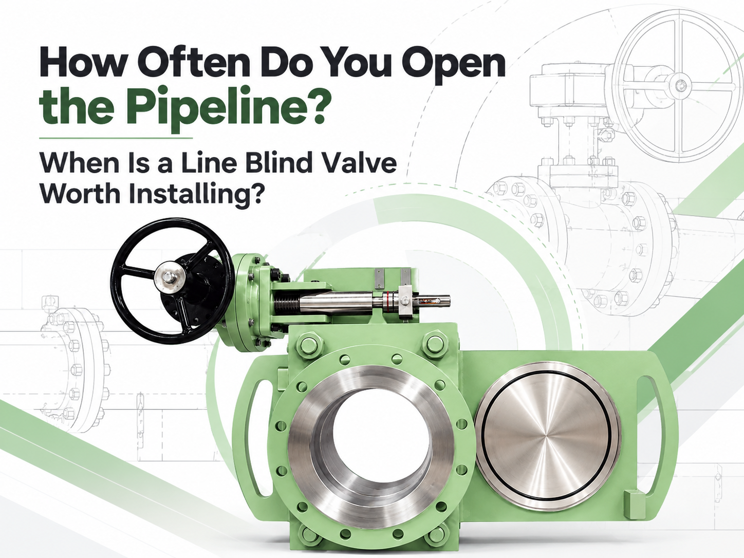
تستحق صمامات عزل الخطي التقييم عندما يتم عزل خط الأنابيب عدة مرات في السنة، أو عندما يتسبب تغيير تقليدي واحد في ساعات من الإغلاق، أو أعمال الرفع، أو التعرض الكبير للمتبقيات الخطرة. لا يوجد عدد دورات عام يضمن استرداد الاستثمار. قد يبرر خط حيوي كبير يتم تشغيله مرتين في السنة الاستثمار، بينما قد لا يبرره خط صغير يسهل الوصول إليه ويتم تشغيله شهريًا. يجب أن يعتمد القرار على تكلفة ومخاطر كل حدث عزل كامل، وليس على التكرار بمفرده. لا توجد قاعدة قياسية تنص على "عمليتين في السنة" يستخدم بعض الموردين تغييرًا أو تغييرين سنويين كحد أدنى للفحص الأول. يمكن أن يبدأ ذلك نقاشًا، ولكنه ليس قاعدة هندسية. للفيزياء والتكرار عواقب مختلفة تمامًا على خط خدمات DN50 وخط غاز معالجة رئيسي DN600. للمراجعة الأولية، تُعد النطاقات التالية مفيدة ولكنها ليست إلزامية: تكرار العزل التفسير الأولي مرة واحدة لكل إغلاق رئيسي أو أقل غالباً ما يكون قرص العزل القابل للإزالة أو قرص العزل المزدوج أكثر اقتصاداً. من مرة إلى ثلاث مرات في السنة قَارن العمالة، والرفع، ومدة التوقف، ومخاطر الوسط بعناية. ربع سنوي إلى شهري إن صمام عزل الخط سريع العمل هو عادة مرشح قوي. أسبوعياً أو أكثر من ذلك يستحق العزل المصمم لغرض معين أو المتبوع بالآلية مراجعة تفصيلية؛ وتأكد أيضاً من أن صمام عزل الخط مناسب لخدمة الدورة المطلوبة. يمكن لتكرار التشغيل المنخفض أن يدعم التركيب عندما يتطلب كل حدث سِقالات، أو رافعة، أو عدة فنيي أنابيب، أو انقطاعاً طويلاً في الإنتاج. وعلى العكس من ذلك، فإن التشغيل المتكرر لا يبرر استخدام صمام عزل الخط إذا كانت العملية لا تستطيع استيعاب ضغطه، أو حرارته، أو مواده، أو احتياجات صيانتها. احسب التغيير الكامل إن عملية العزل التقليدية أكبر بكثير من مجرد تحريك لوحة. فبعد تأمين الخط، يقوم العمال بفك المسامير، وتوسيع وصلة الشفة، والتعامل مع اللوحة العمياء أو الفاصلة، واستعادة الحشوات، وإعادة المحاذاة، وربط الوصلة، وإكمال فحوصات التسرب. وتتطلب الأحجام الكبيرة معدات رفع ووصول إضافية. يحافظ الصمام العمياء السريع للخط على اللوحة النظارية أو الانزلاقية مدعومة داخل التجميع المثبت. عادة ما تشير أدبيات الشركة المصنعة إلى إمكانية التغيير بواسطة شخص واحد في غضون دقائق بدلاً من ساعات العمل المطلوبة للأعمال التقليدية للشفات. تعتبر هذه الأرقام مفيدة للتقييم الأولي، ولكن يجب أن يستخدم حساب المشروع إجراءات المصنع الخاصة وأوقات التوقف المسجلة. استخدم مقارنة بسيطة: التكلفة المتجنبة السنوية = العمليات في السنة × التكلفة المتجنبة لكل عملية قد تتضمن التكلفة المتجنبة ساعات عمل فني الأنابيب، وأعمال الرفع، والسقالات، والحشوات والمسامير، واختبار التسرب، وقيمة الإنتاج للوقت الموفر. احرص على فصل الفئات لتجنب ازدواجية الحساب. قارن التوفير السنوي مع سعر التركيب الإضافي لصمام عزل الخط وتكلفة صيانته. قد تكون المخاطر أهم من فترة الاسترداد البسيطة إن فصل الشفات المتكرر يخلق فرصاً للتعرض للمداس المتبقي، وتلف أسطح الشفات، وسوء المحاذاة، والتحميل غير المتسق للمسامير. وتزداد المخاوف مع الوسائط السامة أو القابلة للاشتعال أو الساخنة أو التي يسهل تفريغها. إن تقليل التعامل مع اللوحة والرؤية الواضحة للوضع قد يبرران استخدام صمام عزل الخط حتى بدون فترة استرداد مالي قصيرة. لا يلغي هذا الحاجة إلى عزل العمليات. عادة ما يتم تشغيل صمامات عزل الخط السريعة فقط بعد إيقاف تشغيل الخط، وخفض ضغطه، وتأمينه. ولا ينبغي أبداً تفسير ...
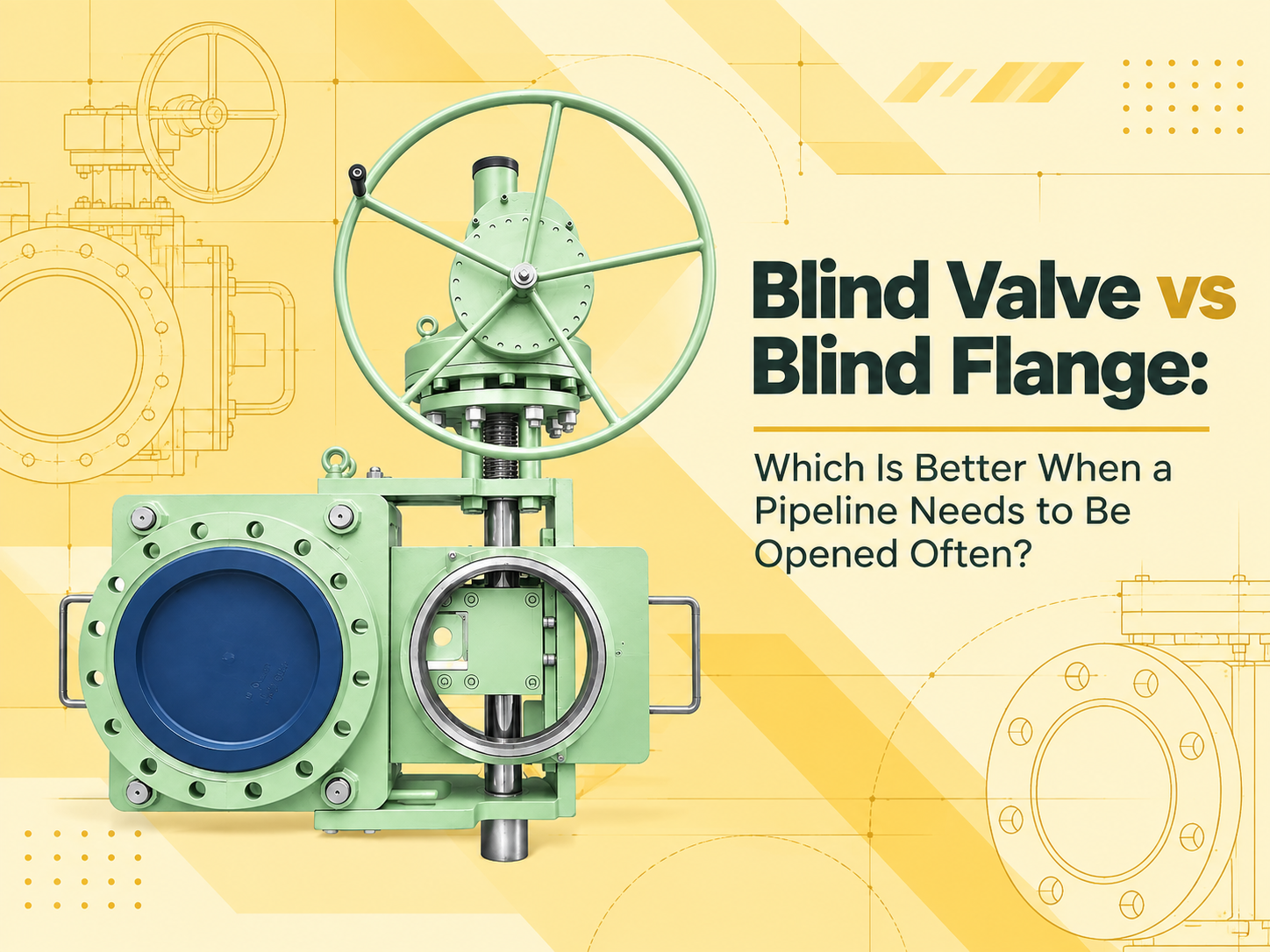
عندما يجب فتح خط الأنابيب وعزله بشكل إيجابي ومتكرر، فإن صمام العزل الأعمى (line blind valve) عادة ما يكون الخيار الأفضل. فهو يبقي آلية العزل مثبتة بشكل دائم ويسمح للمشغلين بالتبديل بين وضعي الفتح والإغلاق دون الحاجة إلى إزالة غطاء طرفي مثبت بمسامير بشكل متكرر. تكلّف الشفة العمياء (blind flange) أقل وتحتوي على أجزاء متحركة أقل، لكنها أكثر ملاءمة لإغلاق طرف أنبوب سيظل مغلقاً لفترات طويلة. تفترض هذه الإجابة أن "الشفة العمياء" تعني شفة صلبة مثبتة بمسامير في نهاية أنبوب أو فوهة. أما العازل النظاري (spectacle blind) أو العازل القابل للإزالة (spade) المثبت بين شفتين فهو جهاز مختلف، على الرغم من أنه ينشئ حاجز عزل معدني صلب مماثل. التغيير المتكرر للفتح يغير حساب التكلفة سعر الشراء يرجح كفة الشفة العمياء. فبناؤها بسيط، وتقتصر الصيانة إلى حد كبير على فحص وجه الشفة، والحشية، والمسامير، والصواميل. إذا كان الإغلاق لن يتم التعامل معه إلا أثناء فترات التوقف العرضية، فمن الصعب التغلب على هذه البساطة. أما الفتح المتكرر فيغير الصورة. تتطلب إزالة الشفة العمياء إيقاف تشغيل الخط، وتفريغ الضغط، وتصريفه أو تطهيره، والتحقق من سلامته. يجب بعد ذلك فك المسامير، ودعم الشفة، وفصل أسطح الإغلاق. قد تتطلب الشفاه الأكبر حجماً معدات رفع. تتطلب إعادة التجميع حشية جديدة، وربطاً محكماً للمسامير، واختباراً للتسرب. لا تعتبر أي من هذه الخطوات غير عادية، لكن تكرارها يحول مكوناً منخفض التكلفة إلى طريقة تشغيل كثيفة العمالة. يتطلب صمام العزل الأعمى أيضاً عزل الخط وتفريغ الضغط منه قبل تغيير وضعه ما لم ينص تصميمه المعتمد وإجراءات تشغيله على خلاف ذلك صراحةً. وتكمن ميزته في المناولة الميكانيكية: حيث يظل اللوح أو الفاصل أو العنصر المنزلق محتجزاً داخل جسم الصمام، وتقوم الآلية بفصل أسطح الإغلاق وتحريكها وإعادة تثبيتها. قد تناسب التروس اليدوية قوى التشغيل المعتدلة؛ بينما قد يكون التشغيل الكهربائي أو الهوائي أو الهيدروليكي مبرراً للأحجام الكبيرة أو التشغيل عن بُعد. صمام العزل الأعمى يقلل من المناولة ولكنه يضيف معدات للصيانة بالنسبة للتبديل المتكرر، يمكن لصمام العزل الأعمى تقصير المهمة وتقليل المناولة المتكررة للألواح والمسامير والحشيات الثقيلة. عادة ما يكون وضع الفتح أو الإغلاق مرئياً من اللوح الخارجي أو مؤشر الوضع، مما يساعد في التحقق الميداني. كما أنه يتجنب إجبار الأنابيب المتصلة على التباعد بشكل متكرر لإدخال أو إزالة العازل. تأتي هذه المزايا مع صيانة إضافية. يجب أن تظل الموجهات، والبراغي، وعلب التروس، والمكونات الهيدروليكية، والأختام، وأقفال التعشيق (interlocks) تعمل بكفاءة. يمكن أن تعيق رواسب المنتج أو التآكل حركة اللوح، بينما يمكن أن تمنع أسطح الإغلاق التالفة إعادة التثبيت الموثوقة. لذلك يحتاج التركيب إلى تصريف، ووصول للتنظيف، وخلوص محيطي كافٍ لإكمال الحركة الكاملة وصيانة الآلية. لا تحتوي الشفة العمياء على آلية تشغيل قد تتعطل. ومع ذلك، فإن الإزالة المتكررة يمكن أن تلحق الضرر بوجوه الشفة، أو تمدد المسامير أو تسبب تآكلها، وتخل بمحاذاة الأنابيب، وتعرض العمال للمواد المتبقية. السؤال ليس ببساطة أي جهاز يحتوي على أجزاء أقل؛ بل هو ما إذا كان التفكيك المتكرر يخلق عملاً ومخاطر أكثر من صيانة صمام عزل أعمى مصمم لهذا الغرض. العزل الإيجابي يعتمد دائماً على الإجراء يمكن لكلا الترتيبين وضع حاجز صلب مقاوم للضغط عبر التجويف. تصف إدارة السلامة والصحة المهنية (OSHA) العزل (blanking or blindi...
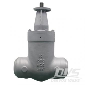
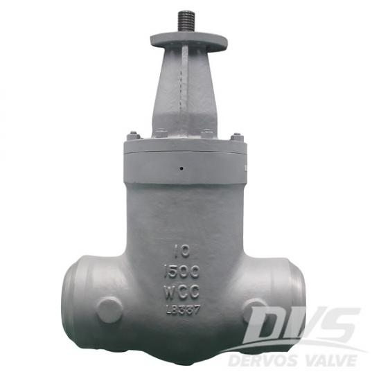
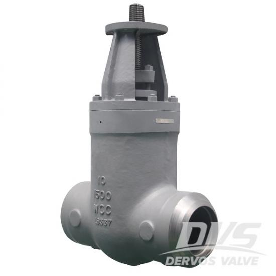
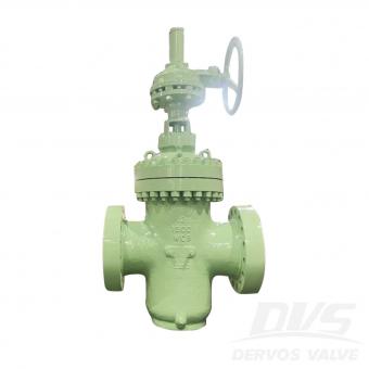
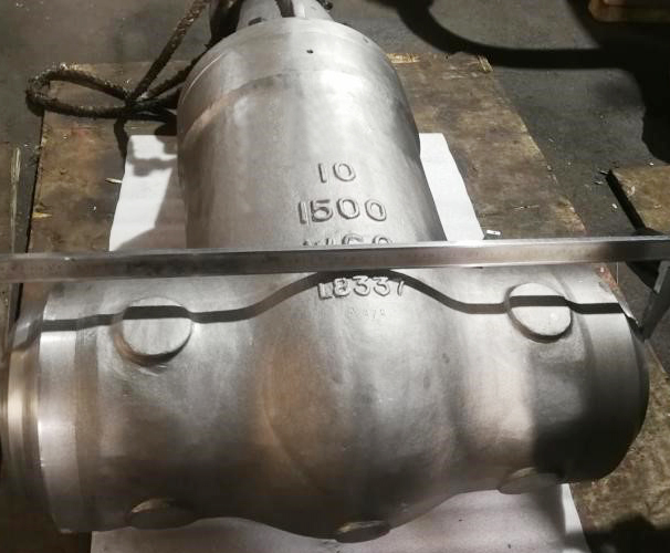
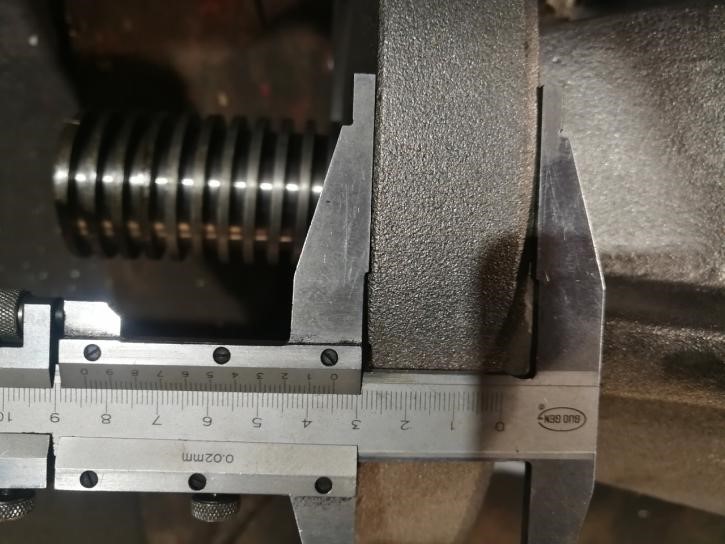
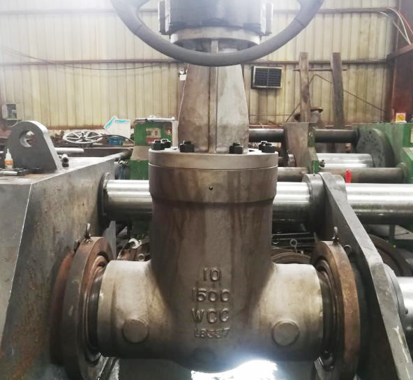
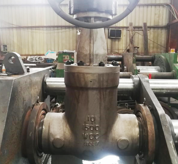
10 '' صمام بوابة 1500LB مصنوع وفقًا لمعيار ASME B16.34. جسم الصمام مصنوع من WCC. تتميز بالخصائص الهيكلية للضغط الذاتي الختم ، والساق الصاعد ، والوتد المرن والطول الهيكلي 864 مم. كلا طرفي جذع الصمام مترابطة. لديها نوع اتصال BW.
دفع:
30% when order confirmed, 70% before shipmentأصل المنتج:
Chinaاللون:
Customizationميناء الشحن:
Shanghai, Chinaالمهلة:
30~60 days Ex Works after order confirmationMaterial:
ASTM A216 WCCMethod of Operation:
Bare Stemوصف المنتج
|
يكتب |
صمام البوابة |
|
بحجم |
10 '' |
|
ضغط |
1500 رطل |
|
مادة الجسم |
ASTM A216 WCC |
|
معيار التصميم |
ASME B16.34 |
|
نوع الصمام |
PSB |
|
تشغيل الصمام |
عارية الجذعية |
|
نوع اتصال النهاية |
BW |
|
بعد نهاية إلى نهاية |
ANSI B16.10.00 تحديث |
|
البعد BW |
ANSI B16.25.0000 |
|
اختبار |
API 598 |
|
متوسط قابل للتطبيق |
الماء والنفط والغاز |
سمات
1. تم إستخدام إسفين مرن ، والذي لديه تعويض مرن معين تحت ظروف الضغط العالي ، وختم أكثر موثوقية.
2. يمكن اختيار هيكل الختم ومواد الختم وفقًا لظروف العمل المختلفة ومتطلبات التحميل المسبق.
رسم تقنى _ رسم عن طريق الكمبيوتر
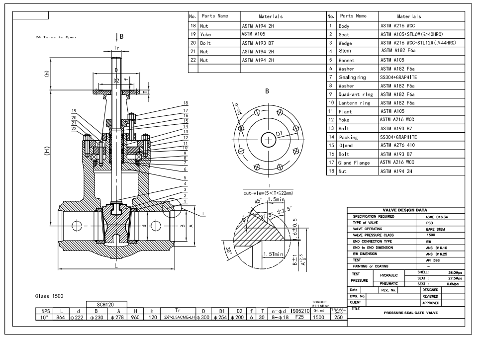
فحص البعد
اختبارات الشهود
لوحة الاسم والتعبئة
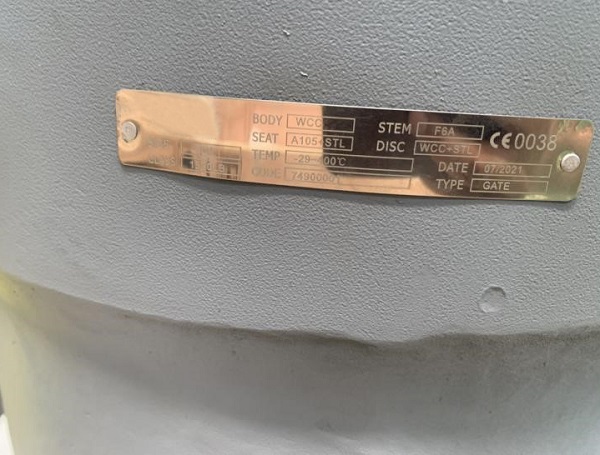
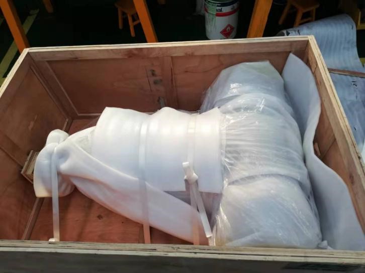
تقرير التفتيش
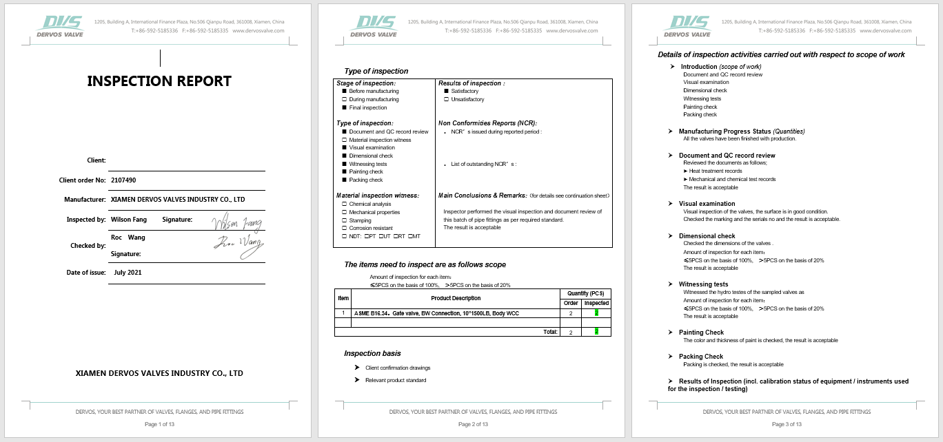
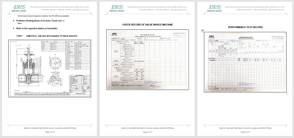
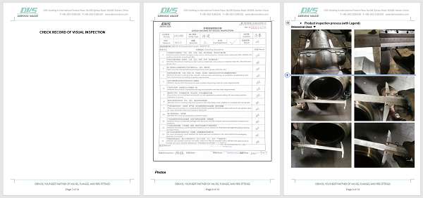
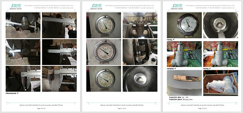
إذا كنت مهتما في منتجاتنا و تريد أن تعرف المزيد من التفاصيل,يرجى ترك رسالة هنا وسوف نقوم بالرد عليك بأسرع ما يمكن.
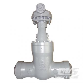
تم تصميم صمام البوابة 2500 فئة 8 بوصات بغطاء مانع للتسرب ، ووصلة لحام بعقب ، وتشغيل علبة التروس. يحتوي صمام البوابة 8 بوصة على جسم WCB من الفولاذ الكربوني وتقليم 5. تفاصيل سريعة نوع بوابة صمام بحجم 8 " ضغط التصميم ansi 2500 اعمال بناء الضغط غطاء الختم ، إسفين مرن ، مقعد من المعدن إلى المعدن نوع الاتصال بعقب اللحام (SW) نوع العملية ناقل الحركة عملية مواد الجسم أ 217 wc6 مواد تقليم تقليم 5 كود التصميم api 600 وجها لوجه البعد اسمى ب 16.10 نهاية الاتصال اسمى ب 16.25 الضغط & أمبير ؛ مؤقت اسمى ب 16.34 متوسط ماء، النفط والغاز الأصل الصين البعد & أمبير ؛ مواد nps dn صف دراسي 2 2 1/2 3 4 6 8 10 12 14 16 18 20 24 50 65 80 100 150 200 250 300 350 400 450 500 600 ل (الترددات اللاسلكية) 900 رطل 368 419 381 457 610 737 838 965 1029 1130 & emsp؛ & emsp؛ & emsp؛ 1500 رطل 368 419 470 546 705 832 991 1130 1257 1384 & emsp؛ & emsp؛ & emsp؛ 2500 رطل 451 508 578 673 917 1022 1270 & emsp؛ & emsp؛ & emsp؛ & emsp؛ & emsp؛ & emsp؛ L1 (وزن الجسم) 900 رطل 216 254 305 355 508 660 787 914 991 1092 1346 1473 1600 1500 رطل 216 254 305 406 559 711 864 991 1067 1194 1697 & emsp؛ & emsp؛ 2500 رطل 279 330 368 457 610 762 914 1041 1118 1245 & emsp؛ & emsp؛ & emsp؛ l2 (rtj) 900 رطل 371 422 384 460 613 740 841 968 1038 1140 & emsp؛ & emsp؛ & emsp؛ 1500 رطل 371 422 473 549 711 841 1000 1146 1276 1407 & emsp؛ & emsp؛ & emsp؛ 2500 رطل 454 514 584 683 927 1038 1292 & emsp؛ & emsp؛ & emsp؛ & emsp؛ & emsp؛ & emsp؛ ح (أوبن) 900 رطل 554 637 680 796 1084 1372 1494 1550 1960 2210 & emsp؛ & emsp؛ & emsp؛ 1500 رطل 554 637 767 875 1094 1372 1655 1834 2150 2260 2460 2721 2940 2500 رطل 610 654 753 850 1254 1374 1685 1894 2226 2382 2585 & emsp؛ & emsp؛ ث 900 رطل 300 350 350 400 560 460 * 610 * 610 * 610 * 760 * & emsp؛ & emsp؛ & emsp؛ 1500 رطل 300 450 450 560 305 * 460 * 610 * 610 * 760 * 760 * & emsp؛ & emsp؛ & emsp؛ 2500 رطل 500 500 600 600 460 * 460 * 610 * & emsp؛ & emsp؛ & emsp؛ & emsp؛ & emsp؛ & emsp؛ الوزن (rf) 900 رطل 50 84 92 154 341 622 950 1295 1720 2380 & emsp؛ & emsp؛ & emsp؛ 1500 رطل 60 91 128 182 394 795 1370 2120 2800 3870 & emsp؛ & emsp؛ & emsp؛ 2500 رطل 121 175 195 229 720 1295 2250 & emsp؛ & emsp؛ & emsp؛ & emsp؛ & emsp؛ & emsp؛ الوزن (وزن الجسم) 900 رطل 39 64 82 120 266 524 760 1090 1450 2018 & emsp؛ & emsp؛ & emsp؛ 1500 رطل 46 71 85 130 292 578 974 1615 2010 2815 3315 4150 5219 2500 رطل 88 135 144 158 500 892 1550 1978 2580 3780 5988 & emsp؛ & emsp؛ * يوصى باستخدام مشغل التروس اليدوي لا. جزء WCB wc6 wc9 ج 5 راجع 8 CF 8M 1 الجسم a216 wcb a217 w6 a217 wc9 a217 c5 a351 cf8 a351 cf8m 2 مقعد a182 f6a a182 f22 a182 f22 a182 f5 a182 f304 a182 f316 3 وتد a216 wcb a217 w6 a217 wc9 a217 c5 a351 cf8 a351 cf8m 4 إيقاف a182 f6a saehnv3 a182 f304 a182 f316 5 مربع حشو a216 wcb a217 w6 a217 wc9 a217 c5 a351 cf8 a351 cf8m 6 ختم Ansi 316l الجرافيت المرن + 316 7 حلقة الانقسام صلب و ٦ و ٦ و ٦ a182 f304 ص 316 8 الحلقة الخلفية صلب صلب صلب صلب SS SS 9 الترباس أ 193 ب 7 أ 193 ب 7 أ 193 ب 7 أ 193 ب 7 أ 193 ب 8 أ 193 ب 8 10 البندق أ 194 2 ساعة أ 194 2 ساعة أ 194 2 ساعة أ 194 2 ساعة أ 194 غرام 8 أ 194 غرام 8 11 نير a216 wcb a217 w6 a217 wc9 a217 c5 a351 cf8 a351 cf8m 12 الترباس أ 193 ب 7 أ 193 ب 7 أ 193 ب 7 أ 193 ب 7 أ 193 ب 8 أ 193 ب 8 13 البندق أ 194 2 ساعة أ 194 2 ساعة أ 194 2 ساعة أ 194 2 ساعة أ 194 غرام 8 أ 194 غرام 8 14 لوحة التعبئة أنسي 410 أنسي 410 أنسي 410 أنسي 410 انسي 304 انسي 316 15 التعبئة الجرافيت مرنة (مضفر وخاتم) أو ptfe 16 انقسام دبوس صلب صلب صلب صلب صلب صلب 17 ييبولت أ 193 ب 7 أ 193 ب 7 أ 193 ب 7 أ 193 ب 7 أ 193 ب 8 أ 193 ب 8 18 السدادة a182 f6 a182 f6 a182 f6 a182 f6 a182 f304 a182 f316 19 شفة الغدة أ 105 أ 105 أ 105 أ 105 a182 f304 a182 f316 20 البندق أ 194 2 ساعة أ 194 2 ساعة أ 194 2 ساعة أ 194 2 ساعة أ 194 غرام 8 أ 194 غرام 8 21 عشيق أ 193 ب 7 أ 193 ب 7 أ 193 ب 7 أ 193 ب
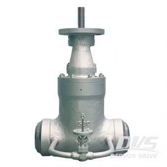
8 " تم تصنيع صمام البوابة 1500 رطل وفقًا لمعيار ASME B16 . 34 القياسي . جسم الصمام مصنوع من WCC . وله الخصائص الهيكلية للضغط الذاتي الختم , بوابة مرنة وطول بنيوي 711 مم . مبدأ العمل لصمام الختم الذاتي هو استخدام سطح إسفيني مانع للتسرب للختم تحت الضغط .
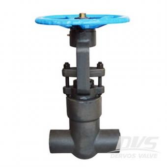
تم تصميم صمام البوابة فئة 4500 عالي الضغط مع وصلة نهاية PSB و SW . مصنوعة من CS A105 , ويتبع صمام البوابة مقاس 2 بوصة معيار الفحص API 598 ومعيار التصميم API 602 . يمكن أن تقدم dervos خدمة التخصيص من خلال تزويد العملاء بصمامات بأحجام مختلفة , المواد , المعايير , ضغط التصميم , الهيكل , نوع العملية ونوع التوصيل .
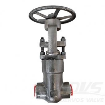
صمام بوابة غطاء المحرك بختم ضغط 2 بوصة، 900 رطل، مصنوع وفقًا لمعيار ASME B16.34. جسم الصمام مصنوع من مادة A182-F91. يتميز بخصائص هيكلية مثل PSB وOS&Y وSolid Wedge. طريقة توصيله هي BW sch 80 ASME B16.25، ويعمل بنظام التشغيل اليدوي.
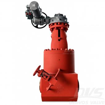
تم تصميم صمام البوابة ذو مانع الضغط F91 بقطر 14 بوصة وضغط 4500LB لخدمة غلايات محطات الطاقة ذات درجات الحرارة العالية والضغط العالي. يتميز بمادة ASTM A182 F91 Type 2، وغطاء علوي بمانع ضغط، وهيكل قرصي مزدوج متوازٍ، ونهايات BW، ومشغل كهربائي AOX، وصمام تجاوز لمعادلة الضغط.
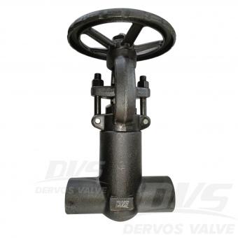
صمام بوابة بختم ضغط 1/2 بوصة 1500LB مصنوع وفقًا لمعيار BS3799. جسم الصمام مصنوع من A105N. يتميز بخصائص هيكلية لختم الضغط. طريقة توصيله هي FNPT. كما أنه مزود بعجلة يدوية.وضع التشغيل. معلمات المنتج النوع صمام بوابة بختم ضغط الحجم 1/2 بوصة الضغط 1500LB التوصيل FNPT التشغيل عجلة يدوية مادة الجسم ASTM A105 معيار التصميم ASME B16.3 المسافة من وجه إلى وجه الخاص بالشركة المصنعة أبعاد النهايات الملولبة (NPT) ASME B1.20.1 رمز الاختبار والفحص API 598 درجة الحرارة -29 ~ 425°C الوسط القابل للتطبيق الماء والزيت والغاز الميزات 1. يوفر غطاء المحور بختم الضغط أداء إحكامًا محسنًا للخدمات ذات الضغط العالي من الفئة 1500. 2. يضمن جسم الفولاذ المطروق A105N والنهايات FNPT مقاس 1/2 بوصة قوة عالية وتركيبًا ملولبًا آمنًا. الرسم الفني فحص الأبعاد اختبار الضغط لوحة الاسم والتعبئة تقرير الفحص


حقوق النشر © 2015-2026 DERVOS VALVE CO.,LTD.كل الحقوق محفوظة مدونة / خريطة الموقع / XML / سياسة الخصوصية