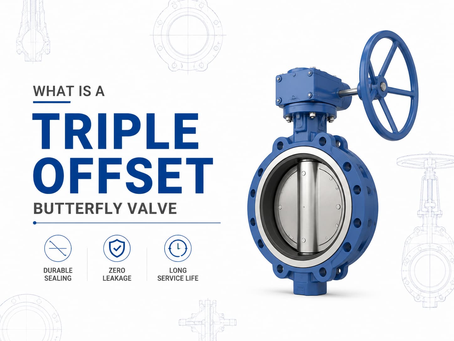
صمام فراشة ثلاثي الانحراف هو صمام عزل عالي الأداء مصمم للتطبيقات التي لا تستطيع فيها صمامات الفراشة التقليدية ذات المقعد المرن أو ذات الانحراف المزدوج تلبية متطلبات الضغط أو درجة الحرارة أو التسرب. وباستخدام تصميم إحكام ثلاثي الانحراف، يحقق الصمام آلية إحكام معدن-إلى-معدن مع تقليل الاحتكاك بين القرص والمقعد أثناء التشغيل، مما يجعله مناسبًا للخدمات الصعبة مثل النفط والغاز والبتروكيماويات وتوليد الطاقة والغاز الطبيعي المسال والبخار وأنظمة العمليات الصناعية. تصميم ومبدأ عمل صمام الفراشة ثلاثي الانحراف على عكس صمام الفراشة متحد المركز، حيث يتم وضع العمود على خط المنتصف للقرص والمقعد، فإن صمام الفراشة ثلاثي الانحراف يدمج ثلاثة انحرافات هندسية مستقلة. ينقل الانحراف الأول العمود بعيدًا عن خط المنتصف لجسم الصمام، بينما يزيح الانحراف الثاني العمود عن خط منتصف خط الأنابيب، ويضيف الانحراف الثالث سطح إحكام مخروطيًا بدلًا من شكل إحكام دائري. تسمح هذه الهندسة للقرص بالابتعاد عن المقعد مباشرة بعد بدء الدوران، مما يلغي الاحتكاك بين أسطح الإحكام. الميزة الرئيسية لهذا التصميم هي أن قوة الإحكام تتولد بواسطة عزم الدوران بدلًا من الضغط المستمر على المواد اللينة. إذا كان التطبيق يتطلب خدمة بدرجات حرارة عالية، فإن صمام الفراشة ثلاثي الانحراف ذو المقعد المعدني يُفضل غالبًا لأن مقاعد المطاط الصناعي قد تتدهور تحت درجات الحرارة المرتفعة. وإذا كان الوسط يحتوي على جسيمات كاشطة أو مواد كيميائية عدوانية، فإن اختيار مواد القرص والمقعد والجسم يصبح أمرًا بالغ الأهمية لمنع التآكل والتلف والتسرب أثناء التشغيل طويل الأمد. معايير ومواد صمام الفراشة ثلاثي الانحراف يُصنع صمام الفراشة ثلاثي الانحراف عادةً وفقًا لمعايير مثل API 609 وEN 593 وISO 5752، مع تصنيفات ضغط تتراوح من الفئة 150 إلى الفئة 600 وما فوق حسب متطلبات التصميم. تشمل المواد النموذجية الفولاذ الكربوني والفولاذ المقاوم للصدأ والفولاذ المقاوم للصدأ المزدوج وبرونز الألومنيوم والسبائك القائمة على النيكل. بالنسبة لتطبيقات مياه البحر المسببة للتآكل، قد يتم اختيار سبائك برونز الألومنيوم مثل C95500 أو C95800، بينما قد تتطلب تطبيقات الخدمة الحامضية مواد متوافقة مع متطلبات NACE MR0175/ISO 15156. أداء إحكام صمام الفراشة ثلاثي الانحراف والتحكم في التسرب يعتمد أداء إحكام صمام الفراشة ثلاثي الانحراف على التفاعل بين حلقة الإحكام وتشطيب سطح المقعد وعزم التشغيل وتوافق المواد. وبما أن أسطح الإحكام تتلامس فقط عند موضع الإغلاق النهائي، فإن التآكل الميكانيكي ينخفض بشكل كبير مقارنة بتصميمات صمامات الفراشة التقليدية. إذا كان التسرب الصفري مطلوبًا للعزل الحرج، فيجب مراعاة تصميم الصمام وفئة الضغط ومعيار التسرب المطبق، مثل API 598 أو ISO 5208، أثناء تحديد المواصفات. تطبيقات صمام الفراشة ثلاثي الانحراف واعتبارات الاختيار في خطوط الأنابيب ذات الأقطار الكبيرة، غالبًا ما يتم اختيار صمامات الفراشة ثلاثية الانحراف كبديل لصمامات البوابة لأنها توفر بُعدًا أقصر من وجه إلى وجه ووزن تركيب أقل. ومع ذلك، يجب أن يعتمد اختيار الصمام على ظروف التشغيل وليس على الحجم فقط. إذا كان خط الأنابيب يتطلب تشغيلًا متكررًا أو مساحة تركيب محدودة أو قدرة إغلاق عند درجات حرارة عالية، فقد يوفر تصميم الانحراف الثلاثي مزايا. وإذا كانت الخدمة تتطلب التحكم بالخنق، فيلزم إجراء تقييم إضافي لخصائص التدفق وحجم المشغل، لأن صمامات الفراشة مُحسّنة عمومًا لتطبيقات العزل والت...
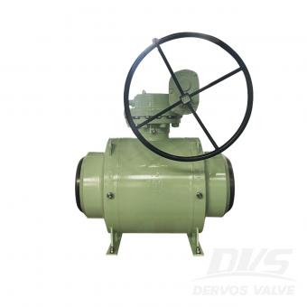
تُعد صمامات الكرة والصمامات السدّادية كلاهما صمامات دوارة ربع دورة تُستخدم للتحكم في التشغيل والإيقاف والعزل في أنظمة الأنابيب الصناعية. وعلى الرغم من أنها تشترك في مبادئ تشغيل متشابهة، فإن تصاميمها الداخلية تؤدي إلى خصائص أداء مختلفة، خاصة من حيث الإحكام، وقدرة تحمل الضغط، وعزم التشغيل، ومتطلبات الصيانة، ومدى ملاءمتها للوسائط المختلفة. يجب أن يعتمد الاختيار بين الصمام الكروي والصمام السدّادي على ظروف التشغيل الفعلية بدلًا من تفضيل نوع الصمام. إذا كان التطبيق يتطلب إغلاقًا محكمًا، وتشغيلًا متكررًا، وعزم تشغيل منخفضًا، فغالبًا ما يُفضّل الصمام الكروي. وإذا كان النظام يتعامل مع وسائط متسخة أو جزيئات كاشطة أو ممرات تدفق كبيرة، فقد يوفر الصمام السدّادي موثوقية أفضل. اختلافات التصميم وأداء الإحكام أحد صمام كروييستخدم عنصر إغلاق كروي الشكل مزودًا بثقب محفور. عندما يكون الصمام مفتوحًا، يتماشى الثقب مع خط الأنابيب لتوفير مسار تدفق شبه غير مقيد. وعند تدويره بزاوية 90 درجة، يحجب الجزء المصمت من الكرة الممر ويوفر الإغلاق. يستخدم الصمام السدّادي سدادة أسطوانية أو مخروطية تحتوي على ممر تدفق عبر المركز. تدور السدادة داخل الجسم للتحكم في التدفق. وبحسب التصميم، يمكن أن تكون الصمامات السدّادية مُزلّقة أو ذات بطانة أو غير مُزلّقة، حيث يوفر كل هيكل خصائص إحكام مختلفة. تُعد آلية الإحكام إحدى الاختلافات الرئيسية بين الصمامين. تستخدم الصمامات الكروية عمومًا مقاعد لينة أو مقاعد معدنية أو مزيجًا من كليهما لتحقيق إغلاق موثوق. إذا كان النظام يتطلب عزلًا محكمًا دون فقاعات، خاصة في خدمة الغاز أو تطبيقات العمليات الحرجة، فإن الصمام الكروي المختار بشكل صحيح يمكن أن يوفر أداء إحكام ممتازًا. تعتمد الصمامات السدّادية على التلامس بين السدادة وجسم الصمام أو البطانة. تستخدم الصمامات السدّادية المُزلّقة مادة مانعة للتسرب تُحقن بين السدادة والجسم لتقليل الاحتكاك وتحسين الإحكام. يمكن لهذا التصميم أن يعمل جيدًا في التطبيقات التي تحتوي فيها الوسائط على ملوثات، لأن مادة الإحكام تساعد على حماية أسطح الإغلاق. اعتبارات التطبيق تحدد ظروف التشغيل ما إذا كان الصمام الكروي أو الصمام السدّاديهو الأكثر ملاءمة. تُستخدم الصمامات الكروية على نطاق واسع في صناعات النفط والغاز والبتروكيماويات والغاز الطبيعي المسال والمعالجة الكيميائية والطاقة حيث يكون الإغلاق الموثوق مطلوبًا. تُستخدم الصمامات الكروية العائمة عادةً في أنظمة الضغط المنخفض، بينما تُفضّل الصمامات الكروية المركبة على مرتكزات الدوران للأحجام الأكبر وتصنيفات الضغط الأعلى لأن دعم مرتكز الدوران يقلل عزم التشغيل. إذا كان الصمام سيتعرض لدورات تشغيل متكررة، فإن الصمام الكروي يوفر عادةً ميزة بسبب تشغيله منخفض الاحتكاك وتفعيله بربع دورة. ومع ذلك، يلزم إجراء دراسة دقيقة عند التعامل مع سوائل تحتوي على جزيئات صلبة. إذا علقت الجزيئات الكاشطة بين الكرة والمقعد، فقد يحدث تلف للمقعد وتسرب. غالبًا ما يتم اختيار الصمامات السدّادية للتطبيقات التي تتضمن سوائل متسخة، ومعلقات، ومياه صرف، وخطوط الأنابيبحيث قد تحتوي وسائط التدفق على مواد صلبة عالقة. يقلل ممر التدفق الكبير والمستقيم من خطر الانسداد. إذا كان مائع العملية يحتوي على ملوثات قد تتسبب في تلف مواد الإحكام اللينة، فقد يوفر الصمام السدّادي ذو المقعد المعدني أو المُزلّق أداء خدمة أفضل. تُعد درجة الحرارة والضغط أيضًا من العوامل المهمة. إذا كان التطبيق يتضمن ضغطًا مرتفعًا أو درجة حرار...

في عام 2026، تحتفل DERVOS VALVE بفخر بالذكرى السنوية الثامنة عشرة، مما يشكّل محطة مهمة في مسيرة الشركة. وللاحتفال بهذه المناسبة، نظّمت DERVOS VALVE احتفالًا بالذكرى السنوية استمر ثلاثة أيام، جمع جميع الموظفين للتأمل في إنجازات الشركة خلال الثمانية عشر عامًا الماضية، والنظر إلى التطور المستقبلي، وتعزيز تماسك الفريق من خلال أنشطة ذات معنى وتجارب مشتركة. استعراض 18 عامًا من النمو من إدارة المواد الخام والتشغيل الآلي الدقيق إلى التجميع واختبار المنتجات، تعكس كل مرحلة من مراحل الإنتاج DERVOS VALVEالتزامها الثابت بالجودة. على مدى الثمانية عشر عامًا الماضية، واصلت DERVOS VALVE تحسين نظام التصنيع لديها مع تعزيز جودة المنتجات وقدرات خدمة العملاء. واليوم تُستخدم صماماتنا الصناعية على نطاق واسع في قطاعات النفط والغاز، والصناعات الكيميائية، وتوليد الطاقة، ومعالجة المياه، LNG، وقطاعات صناعية أخرى، لتوفير حلول صمامات موثوقة للعملاء حول العالم. بناء توافق من أجل التطور المستقبلي أثناء احتفال الذكرى السنوية، عقدت DERVOS VALVE أيضًا اجتماع التواصل لنصف العام. استعرض الاجتماع أداء الشركة خلال النصف الأول من العام وحدد الأهداف الرئيسية للتطور المستقبلي. وتبادل ممثلون من مختلف الأقسام رؤى حول الإنتاج الإدارة، وتحسين الجودة، والتعاون بين الوظائف المختلفة، مع تبادل الخبرات العملية، ومراجعة الإنجازات، ومناقشة الأهداف المستقبلية معًا. عزّز الاجتماع كذلك التواصل بين الأقسام، ورسّخ توافق الفريق، وأضفى زخمًا جديدًا على التطور طويل الأمد للشركة. الاستمتاع بالطبيعة معًا بالإضافة إلى أنشطة الذكرى السنوية للشركة، نظّمت DERVOS VALVE رحلة جماعية للاستمتاع بجمال الطبيعة. وسط مناظر طبيعية خلابة، استمتع الموظفون بالبيئة الجميلة واستكشفوا الثقافة المحلية في أجواء مريحة وممتعة. وقد أتاحت الرحلة فرصة للاسترخاء مع تعزيز العلاقات بين الزملاء. لقد أثرت هذه التجر�
دفع:
30% T/T When Order, 70% T/T Before Shipmentأصل المنتج:
Chinaاللون:
Customizationميناء الشحن:
Shanghai Chinaالمهلة:
35~60 days Ex Works After Order ConfirmationMaterial:
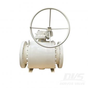
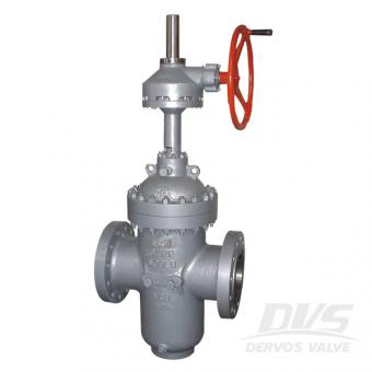
Carbon SteelMethod of Operation:
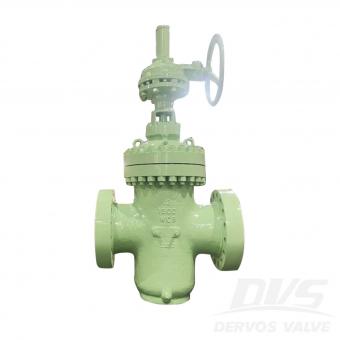
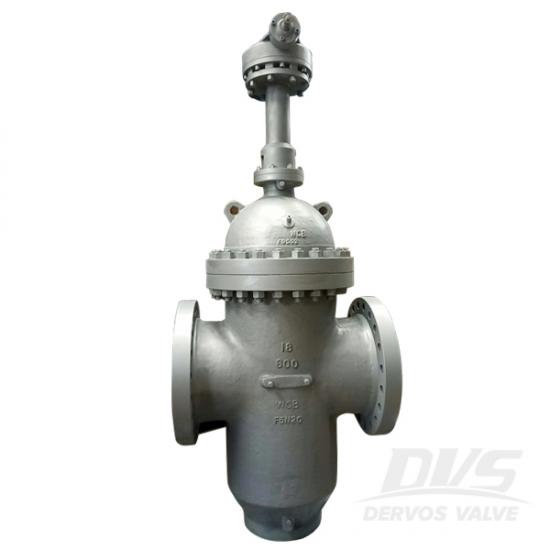
Gear Operatedتم تصميم api 6d من خلال صمام بوابة القناة مع أسافين متوسعة مزدوجة ، ومعدن إلى مقعد معدني وفتحة تحويل للخنازير. يتمتع الصمام بأداء جيد على الختم ، ومقاومة أقل للتدفق ومناسب للتطبيق مع بعض المواد الصلبة أو الجسيمات.
تفاصيل سريعة
|
نوع |
بوابة صمام |
|
بحجم |
18 بوصة |
|
ضغط التصميم |
ansi 600 |
|
اعمال بناء |
مزدوج تمدد الأوتاد ، مقعد معدني بالكامل ، مع فتحة تحويل |
|
نوع الاتصال |
rtj شفة |
|
نوع العملية |
ناقل الحركة تعمل |
|
مواد الجسم |
WCB |
|
مادة إسفين |
a105 + stl + enp |
|
المواد الجذعية |
17-4 ساعة |
|
مواد المقعد |
a105 + stl + enp |
|
كود التصميم |
واجهة برمجة التطبيقات 6 د |
|
وجها لوجه البعد |
اسمى ب 16.10 |
|
نهاية الاتصال |
اسمى ب 16.5 |
|
الضغط & أمبير ؛ مؤقت |
اسمى ب 16.34 |
|
متوسط |
ماء، النفط والغاز |
|
الأصل |
الصين |


إذا كنت مهتما في منتجاتنا و تريد أن تعرف المزيد من التفاصيل,يرجى ترك رسالة هنا وسوف نقوم بالرد عليك بأسرع ما يمكن.
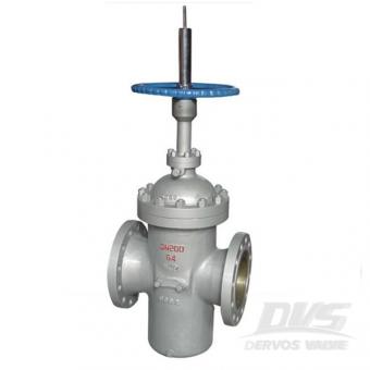
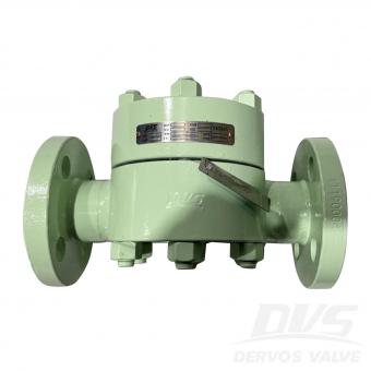
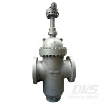
يحتوي صمام بوابة بلاطة القناة المصممة وفقًا لمعيار الدين على فتحة تحويل لتنظيف خط الأنابيب. صمام بوابة القرص الموازي pn64 مصنوع من الفولاذ الكربوني مع شفة RF وعجلة اليد. تفاصيل سريعة نوع موازى صمام بوابة بلاطة القطر الاسمي د 200 الضغط الاسمي ص 64 اعمال بناء موازى صمام بوابة بلاطة ، مع فتحة تحويل ، غطاء محرك مثبت ، مقعد مرن الإتصال شفة عملية عقارب عملية مواد الجسم كربون صلب متوسط ماء، النفط والغاز الأصل الصين ميزة التصميم1. قرص parellel2.Soft مقعد ومقعد معدني للخيارات3. تصميم تجويف كامل للفرشاة وانخفاض ضغط أقل4. تصميم آمن من الحرائق5. وظيفة تخفيف النفس6. الشحوم المناسب للمقعد والساق7. كتلة مزدوجة وقدرة تنزف8. مع منفذ تنفيس وتصريف9. أداء ختم ضيق مواد جزء اسم مواد الجسم & أمبير ؛ غطاء محرك السيارة a216 wcb، cf8، cf8m، cf3، CF3M وتد سبائك الصلب (الوجه تصلب المعالجة) ، الفولاذ المقاوم للصدأ (مع تراكب مشترك) إيقاف سبائك الصلب (الوجه معالجة مقاومة للتآكل) مقعد سبائك الصلب (الوجه تصلب معالج ، مصنوع من البلاستيك) ، فولاذ (مع طبقة متراكبة ، أفضل من البلاستيك) التعبئة السليكوون يا الدائري nbr ، fep شحم مانع للتسرب & emsp؛
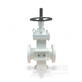
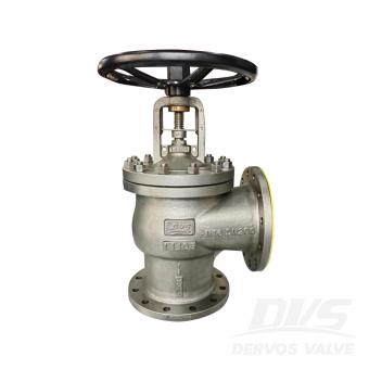
العامل DN100 من خلال صمام بوابة أردواز القناة مصنوع وفقًا لـ EN558.It مثالي لتطبيقات خطوط الأنابيب التي تتطلب قدرة
إنه عبارة عن بوابة مسطحة من الصلب الكربوني بالكامل مع إسفين متوازي ، DN250 PN100 ، مصنوع من LCC ، وهو نوع واحد من الفولاذ الكربوني منخفض الحرارة ، مما يجعل هذا الصمام قادرًا على التعامل مع ظروف العمل القاسية.
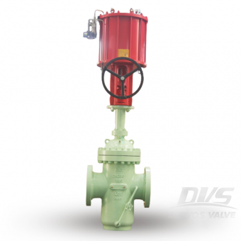
تم تصميم صمام بوابة القناة API 6D مع شفة 600 رطل ووصلة علبة التروس . مصنوعة من الفولاذ الكربوني WCB , صمام البوابة مقاس 20 بوصة ذو تصميم مقعد ناعم بدون فتحة تحويل .
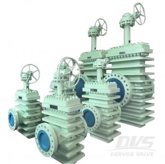
10 '' ~ 24 '' صمام البوابة 600LB مصنوع وفقًا لمعيار API 6D. جسم الصمام مصنوع من A516 Gr70. لها الخصائص الهيكلية للبوابة المتوازية. وضع التشغيل هو تشغيل التروس.
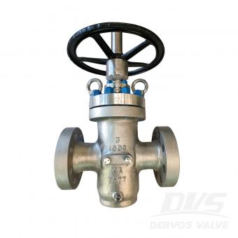
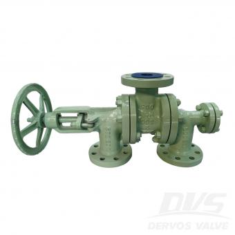
تم تصنيع صمام البوابة المسطحة 3 بوصة 1500 رطل وفقًا لمعيار API6D. جسم الصمام مصنوع من ASTM A995 4A. إنه يتميز بالخصائص الهيكلية لـ BB وOS&Y، مع فتحات التحويل. وضع الاتصال الخاص به هو RTJ. وله وضع تشغيل العجلة اليدوية .


حقوق النشر © 2015-2026 DERVOS VALVE CO.,LTD.كل الحقوق محفوظة مدونة / خريطة الموقع / XML / سياسة الخصوصية